Hydraulic system for molding machine, in particular for press casting machine

A hydraulic system and molding machine technology, applied in mechanical equipment, fluid pressure actuating devices, servo motors, etc., can solve problems such as damaged components, and achieve the effect of reducing service life

Active Publication Date: 2019-06-07
ROBERT BOSCH GMBH
View PDF7 Cites 4 Cited by
  • Summary
  • Abstract
  • Description
  • Claims
  • Application Information

AI Technical Summary

Problems solved by technology

Components may be damaged here

Method used


Image

  • Hydraulic system for molding machine, in particular for press casting machine
  • Hydraulic system for molding machine, in particular for press casting machine
  • Hydraulic system for molding machine, in particular for press casting machine

Examples


Embodiment Construction

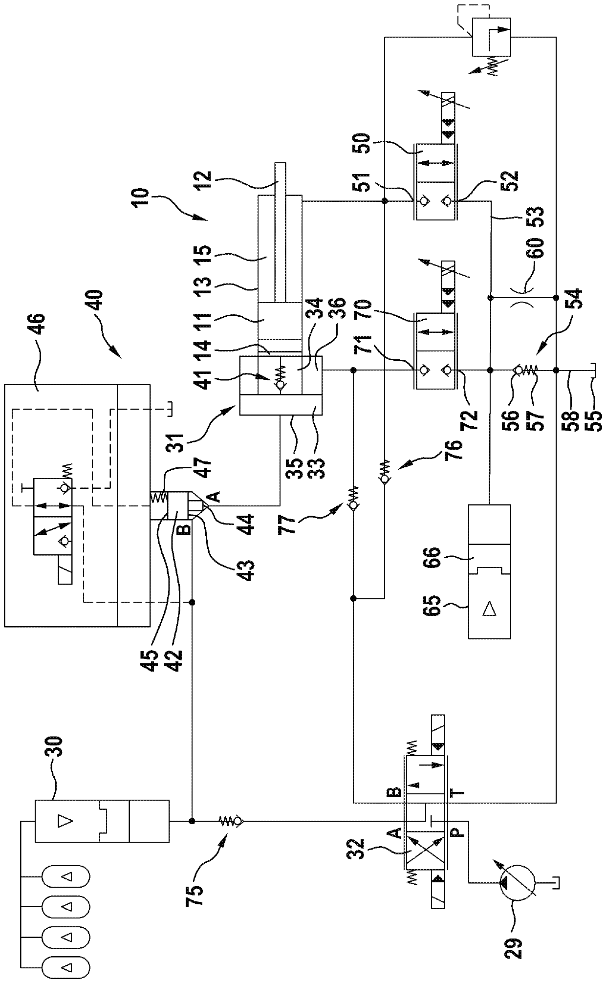
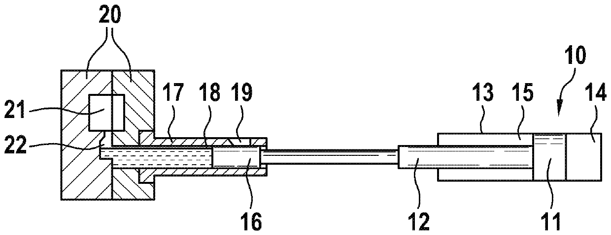
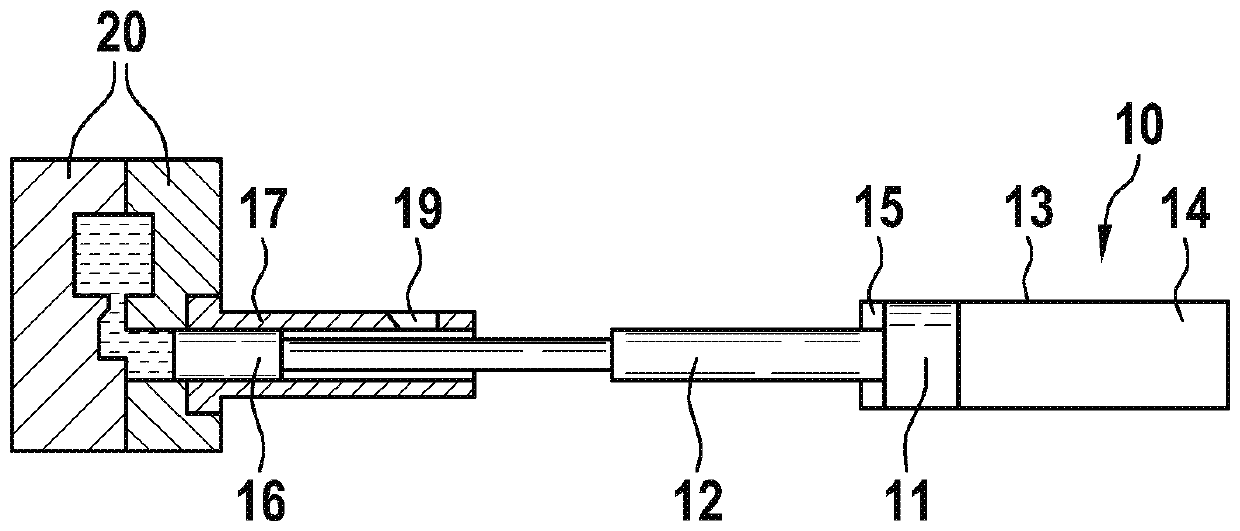
[0027] according to Figures 1 to 4 , the die-casting machine comprises an injection cylinder, which is hereinafter referred to as casting cylinder 10 because of its application in the die-casting machine, and which is configured as a differential cylinder and has a piston 11 and a piston rod 12, which from One side of the piston 11 begins to extend through the interior of the casting cylinder and out of the housing 13 of the casting cylinder on the cover. The completely cylindrical bottom-side pressure chamber 14 and the annular rod-side pressure chamber 15 are separated from one another in the interior of the casting cylinder 10 by the piston 11 .

[0028] Fastened to the piston rod 12 is a cast piston 16 which is linearly displaceable in a spray chamber 18 formed in a spray sleeve 17 . A filling opening 19 is located in the injection sleeve 17 for the liquid or pasty forming material from which the workpiece to be formed is to be formed. The injection sleeve 17 is assembl...


PUM


Abstract

The invention relates to a hydraulic system. The hydraulic system is used for the forming machine. Die-casting machine, in particular for a die-casting machine, the hydraulic system comprises a pressure medium source; a tank, an injection cylinder and an outflow valve, the injection cylinder is provided with a piston; the first pressure chamber acts in the moving-out direction of the piston rod; wherein a pressure medium can be conveyed from the pressure medium source to the first pressure chamber, The outflow valve has a high-pressure connection and a low-pressure connection that can be connected to the high-pressure connection and is connected by means of the high-pressure connection to an annular second pressure chamber that acts in the direction of displacement of the piston rod of theinjection cylinder, and a fluid path is guided from the low-pressure connection of the outflow valve to the tank.

Description

technical field [0001] The invention relates to a hydraulic system which is provided for a molding machine, in particular for a die-casting machine, and which comprises a pressure medium source, a tank, an injection cylinder and an outflow valve, the injection cylinder having Piston, piston rod and has a first pressure chamber acting in the direction of removal of the piston rod, pressure medium can be fed from the pressure medium source to the first pressure chamber, the outflow valve has a high pressure connection and can The low-pressure port connected to the high-pressure port and the outflow valve is connected with the high-pressure port to an annular second pressure chamber acting in the direction of movement of the piston rod of the injection cylinder, and the fluid path starts from its low-pressure port Guide to the tank. Background technique [0002] Such hydraulic systems for die-casting machines are known, for example, from DE 19 49 360 A1, from DE 10 2004 023 15...

Claims


Application Information

Patent Timeline
Patent Type & Authority Applications(China)
IPC IPC(8): F15B11/08F15B13/04B22D17/32
CPCB22D17/2015B22D17/32F15B2211/20546F15B2211/625F15B2211/30505F15B2211/31576F15B2211/31558F15B2211/40507F15B2211/41554F15B2211/214F15B11/036F15B11/0325F15B2211/775F15B2211/8609
Inventor D-W.赫罗尔德H.恩格特
Owner ROBERT BOSCH GMBH
Why Eureka
Try Eureka