
Anti-cracking plate type cooler

A plate cooler and anti-cracking technology, applied in the heat exchanger shell, heat exchange equipment, flushing and other directions, can solve the problems of inconvenient fixed installation, scaling, flushing, etc., to facilitate disassembly and maintenance, prevent local cracking, The effect of easy fixed installation

Inactive Publication Date: 2019-06-07
JIANGSU PEACE POWER MACHINERY
View PDF0 Cites 0 Cited by
  • Summary
  • Abstract
  • Description
  • Claims
  • Application Information

AI Technical Summary

Problems solved by technology

[0002] The plate cooler has the advantages of high heat transfer coefficient, large logarithmic average temperature difference, small footprint, easy to change heat transfer area or process combination, light weight, low price, convenient production, easy cleaning, small heat loss, and not easy to scale. , so it is widely used in refrigeration, HVAC, chemical industry, machinery industry, electric power industry, petroleum, medicine, seawater desalination and ships and other fields. In the existing cooler, the copper tubes circulating the hot and cold medium are staggered, which is beneficial to carry out For effective heat exchange, due to the staggered arrangement of pipes, the processing technology of the cooler is more complicated, but in some cold and heat exchange occasions with small temperature differences, such high-efficiency heat exchangers are not needed, and the use of such staggered pipes for heat exchange Obviously, the cost of the device has increased. At the same time, the existing device is not easy to wash and needs to be disassembled, which increases the labor intensity. The key is that it is not convenient for fixed installation.

Method used


Image

  • Anti-cracking plate type cooler
  • Anti-cracking plate type cooler

Examples


Embodiment Construction

[0013] The following will clearly and completely describe the technical solutions in the embodiments of the present invention with reference to the accompanying drawings in the embodiments of the present invention. Obviously, the described embodiments are only some, not all, embodiments of the present invention. Based on the embodiments of the present invention, all other embodiments obtained by persons of ordinary skill in the art without making creative efforts belong to the protection scope of the present invention.

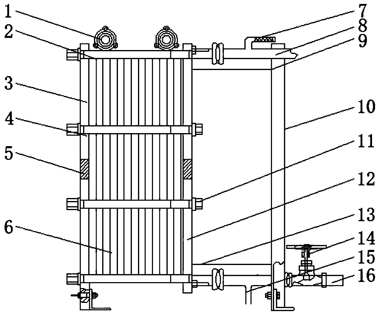
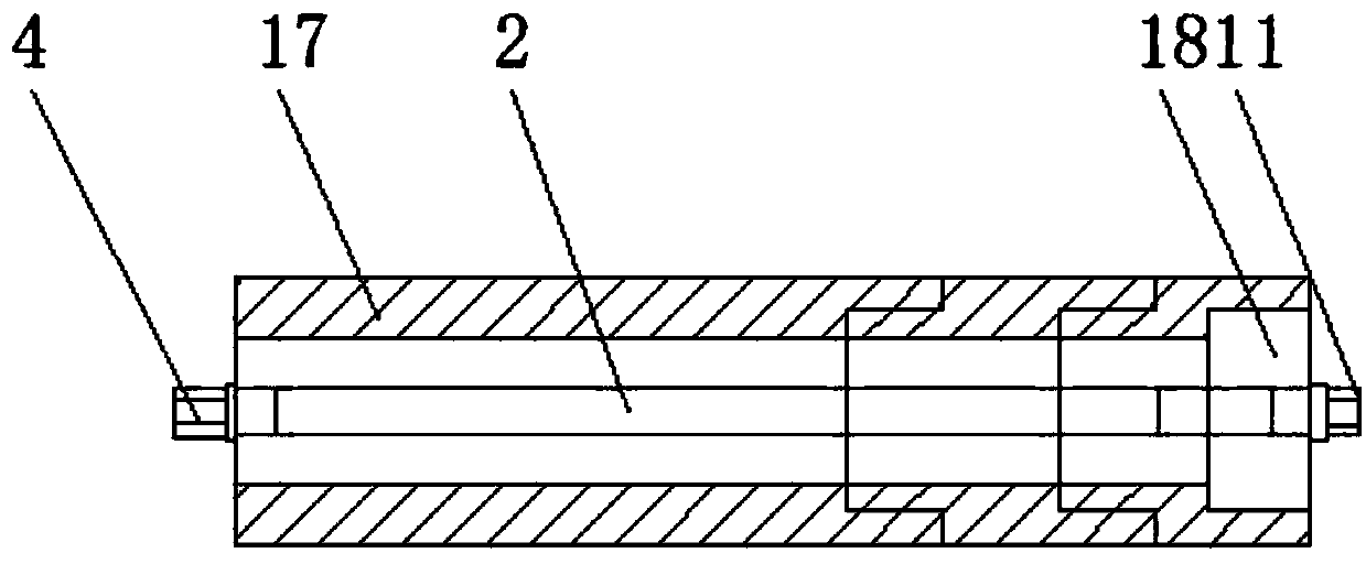
[0014] see Figure 1-2 , an embodiment provided by the present invention: a crack-resistant plate cooler, including a fixed compression plate 3, a cooler body 4, a cooling core 6 and a movable clamping plate 12, and one side of the cooler body 4 is installed There is a fixed compression plate 3, and a flange 1 is installed on the top of the cooler body 4, which makes the device easy to be fixed and installed. The other side of the cooler body 4 is equipped wit...


PUM


Abstract

The invention discloses an anti-cracking plate type cooler. The anti-cracking plate type cooler comprises a fixed pressing plate, a cooler body, cooling core bodies and a movable clamping plate. One side of the cooler body is provided with the fixed pressing plate; the other side of the cooler body is provided with the movable clamping plate; the cooling core bodies are uniformly installed insidethe cooler body; clamping studs are transversely fixed inside the cooler body through bolts; a distance pipe body is arranged on the outer side of each clamping stud, and a distance pipe short piece is arranged inside each distance pipe body; one end of each distance pipe body is connected with one side of the fixed pressing plate; and the other end of each distance pipe body is connected with oneend of the corresponding distance pipe short piece. According to the anti-cracking plate type cooler, a high-pressure nitrogen flushing pipe is arranged at the top end of a cooling water outlet pipe,and a water outlet is formed in the bottom end of a cooling water inlet pipe, so that dirt and impurities on the cooling core bodies can be conveniently cleaned by high-pressure water mist formed bya refrigerant, and cleaning without disassembling is realized.

Description

technical field [0001] The invention relates to the technical field of plate coolers, in particular to a crack-resistant plate cooler. Background technique [0002] The plate cooler has the advantages of high heat transfer coefficient, large logarithmic average temperature difference, small footprint, easy to change heat transfer area or process combination, light weight, low price, convenient production, easy cleaning, small heat loss, and not easy to scale. , so it is widely used in refrigeration, HVAC, chemical industry, machinery industry, electric power industry, petroleum, medicine, seawater desalination and ships and other fields. In the existing cooler, the copper tubes circulating the hot and cold medium are staggered, which is beneficial to carry out For effective heat exchange, due to the staggered arrangement of pipes, the processing technology of the cooler is more complicated, but in some cold and heat exchange occasions with small temperature differences, such...

Claims


Application Information

Patent Timeline
Patent Type & Authority Applications(China)
IPC IPC(8): F28G9/00F28F9/10
Inventor 张凡飞魏纲
Owner JIANGSU PEACE POWER MACHINERY
Learn More