Detection and fixing device for multi-tube optical fiber light guiding bundle

A technology of fixing device and detection device, which is applied in the direction of measuring device, optical instrument test, machine/structural component test, etc., can solve the problems of poor detection effect of optical fiber guide beam flexibility and detachment of optical fiber guide beam.

Inactive Publication Date: 2019-06-07
NANJING HECHO TECH CO LTD
View PDF1 Cites 3 Cited by
  • Summary
  • Abstract
  • Description
  • Claims
  • Application Information

AI Technical Summary

Problems solved by technology

[0005] In order to solve the above problems, the present invention provides a multi-tube optical fiber light guide detection and fixing device, which can solve the problem that the outer end of the optical fiber light guide needs to be manually held when the existing multi-tube optical fiber light guide is detected. During the flexibility test, the optical fiber light guide has hidden dangers of falling off, and the manual inspection of the fiber optic light guide has poor flexibility. It can realize the function of locking and testing multiple optical fiber light guides. There is no hidden danger of the optical fiber guide beam falling off when the optical fiber guide beam is used for flexibility testing, and the mechanization of the optical fiber guide beam for flexibility testing has the advantages of good results, etc.

Method used


Image

  • Detection and fixing device for multi-tube optical fiber light guiding bundle
  • Detection and fixing device for multi-tube optical fiber light guiding bundle
  • Detection and fixing device for multi-tube optical fiber light guiding bundle

Examples


Embodiment Construction

[0031] In order to make the technical means, creative features, goals and effects achieved by the present invention easy to understand, the present invention will be further described below in conjunction with specific illustrations. It should be noted that, in the case of no conflict, the embodiments in the present application and the features in the embodiments can be combined with each other.

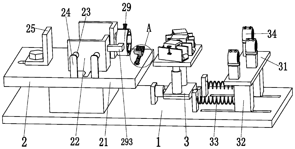
[0032] Such as Figure 1 to Figure 7 As shown, a multi-tube optical fiber light guide detection and fixing device includes a detection base plate 1, a fixing device 2 and a detection device 3. The device 2 and the detection device 3 are installed on the top of the right end of the detection base plate 1 .

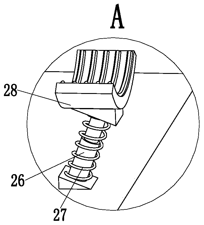
[0033] Described fixing device 2 comprises fixing bracket 21, locking frame 22, locking cylinder 23, locking even pull 24, side support plate 25, supporting telescoping rod 26, supporting spring 27, supporting arc-shaped plate 28 and locking mechanism 29, fixing bracket 21 is inst...


PUM


Abstract

The invention relates to a detection and fixing device for a multi-tube optical fiber light guiding bundle. The device comprises a detecting bottom plate, a fixing device and a detecting device; sliding slots are formed in the right end of the detecting bottom plate; the top end of the left end of the detecting bottom plate is provided with a fixing device; the detecting device is installed on thetop of the right end of the detecting bottom plate; the fixing device comprises a fixing bracket, locking brackets, locking air cylinders, locking connecting plates, a side supporting plate, a supporting telescopic rod, a supporting spring, a supporting curved plate and a locking mechanism; and the detecting device comprises a clamping supporting plate, clamping slide columns, return springs, clamping mechanisms, a detecting motor, a detecting rotating shaft, a detecting air cylinder, a detecting support plate, a detecting mechanism and a rotating shaft connecting plate. According to the prior art, when a multi-tube optical fiber light guiding bundle is detected, the outer end of the optical fiber light guiding bundle needs to be manually held; when the flexibility of the optical fiber light guiding bundle is detected, the risk of the falling off of the optical fiber light guiding bundle may be brought about; and the detection effect of the manual detection of the flexibility of the optical fiber light guiding bundle is poor; and with the detection and fixing device of the invention adopted, the above problems in the prior art can be solved.

Description

technical field [0001] The invention relates to the technical field of optical fiber light guide, in particular to a detection and fixing device for multi-tube optical fiber light guide. Background technique [0002] Fiber optic light guide is a kind of light guide equipment produced by the principle of "total reflection" of optical fiber. The fiber optic light guide is divided into one-input-multiple-out and multi-input-multiple-out specifications. The more commonly used fiber optic light guide is one-input and three-out The optical fiber guide light is generally made of low-loss plastic optical fiber, glass optical fiber and quartz optical fiber. It is widely used in industrial automation, medical treatment, optics, scientific research, display lighting and other industries. The optical fiber guide light is installed on the external machine of the light guide. It can play the role of providing a light source for the optical fiber guide beam. The toughness of the optical fi...

Claims


Application Information

Patent Timeline
Patent Type & Authority Applications(China)
IPC IPC(8): G01M11/00G01M11/08
Inventor 司徒桂平姜白生
Owner NANJING HECHO TECH CO LTD
Why Eureka
Try Eureka