Optical imaging lens
An optical imaging lens and imaging technology, applied in the field of lenses, can solve the problems of not being able to satisfy long focal length, no distortion and high resolution at the same time, and achieve the effect of good night vision, small back focus change, and long focal length
- Summary
- Abstract
- Description
- Claims
- Application Information
AI Technical Summary
Problems solved by technology
Method used
Image
Examples
Embodiment 1
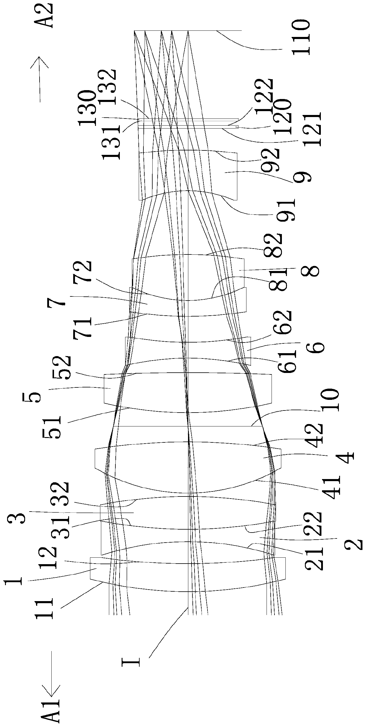
[0077] Such as figure 1 As shown, the present invention discloses an optical imaging lens, which sequentially includes a first lens 1, a second lens 2, a third lens 3, a fourth lens 4, and a diaphragm along an optical axis I from the object side A1 to the image side A2. 10. The fifth lens 5, the sixth lens 6, the seventh lens 7, the eighth lens 8, the ninth lens 9 and the imaging surface 110; the first lens 1 to the ninth lens 9 each include a lens facing the object side A1 and making The object side through which the imaging light passes and an image side facing the image side A2 and allowing the imaging light to pass through;
[0078] The first lens 1 has a positive refractive power, the object side 11 of the first lens 1 is a convex surface, and the image side 12 of the first lens 1 is a concave surface;
[0079] The second lens 2 has a negative refractive power, the object side 21 of the second lens 2 is concave, and the image side 22 of the second lens 2 is concave;
[...
Embodiment 2
[0096] Such as Figure 7 As can be seen, the concave-convex surface and refractive index of each lens in this embodiment and the first embodiment are the same, and only the optical parameters such as the radius of curvature of the lens surface and the thickness of the lens are different.
[0097] The detailed optical data of this specific embodiment are shown in Table 2-1.
[0098] Detailed optical data of Table 2-1 Example 2
[0099]
[0100]
[0101] For the values of other relevant conditional expressions in this specific embodiment, please refer to Figure 25 .
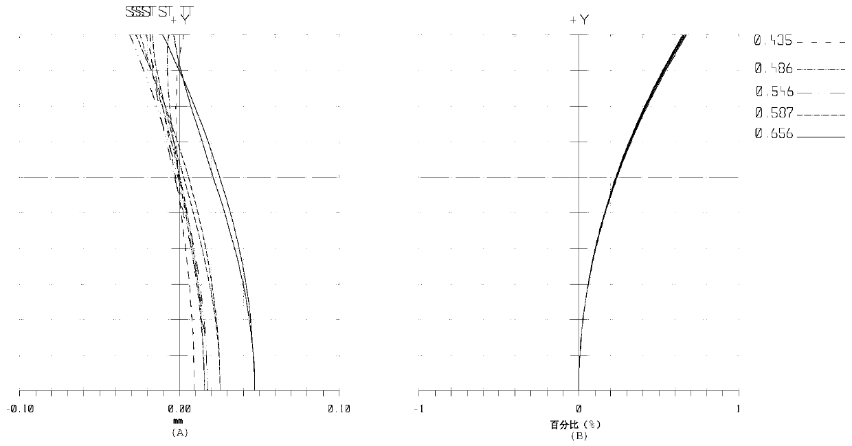
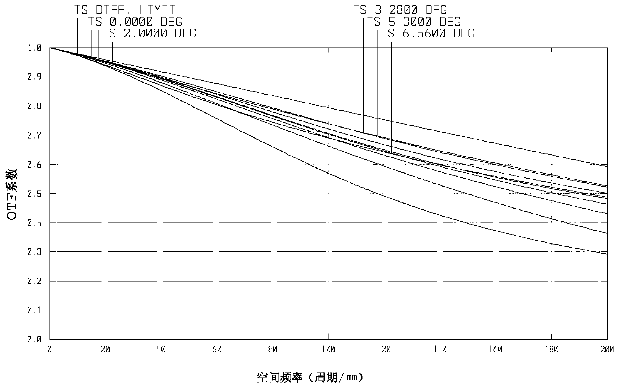
[0102] Field curvature and distortion diagrams of this specific embodiment are as follows Figure 8 As shown in (A) and (B), it can be seen that the distortion is small; for resolution, please refer to Figure 9 with 10 , it can be seen from the figure that the resolution is good and the resolution is high; for visible and infrared 850nm confocal properties, please refer to Figure 11 with 12 , it c...
Embodiment 3
[0105] Such as Figure 13 As can be seen, the concave-convex surface and refractive index of each lens in this embodiment and the first embodiment are the same, and only the optical parameters such as the radius of curvature of the lens surface and the thickness of the lens are different.
[0106] The detailed optical data of this specific embodiment are shown in Table 3-1.
[0107] Detailed optical data of the third embodiment of table 3-1
[0108]
[0109]
[0110] For the values of other relevant conditional expressions in this specific embodiment, please refer to Figure 25 .
[0111] Field curvature and distortion diagrams of this specific embodiment are as follows Figure 14 As shown in (A) and (B), it can be seen that the distortion is small; for resolution, please refer to Figure 15 with 16 , it can be seen from the figure that the resolution is good and the resolution is high; for visible and infrared 850nm confocal properties, please refer to Figure 1...
PUM
 Abstract
Description
Claims
Application Information
 - R&D
- Intellectual Property
- Life Sciences
- Materials
- Tech Scout
- Unparalleled Data Quality
- Higher Quality Content
- 60% Fewer Hallucinations
Browse by: Latest US Patents, China's latest patents, Technical Efficacy Thesaurus, Application Domain, Technology Topic, Popular Technical Reports.
© 2025 PatSnap. All rights reserved.Legal|Privacy policy|Modern Slavery Act Transparency Statement|Sitemap|About US| Contact US: help@patsnap.com


