Image source module, waveguide, near-eye display system and control method thereof

A near-eye display, image source technology, applied in optical components, optics, instruments, etc., can solve problems such as image display, and achieve the effect of reducing swing, reducing system power consumption and component loss

Inactive Publication Date: 2019-06-07
CHENGDU IDEALSEE TECH
View PDF2 Cites 8 Cited by
  • Summary
  • Abstract
  • Description
  • Claims
  • Application Information

AI Technical Summary

Problems solved by technology

[0004] The purpose of this application is to provide an image source module, waveguide, near-eye display system and its control method, which are used to solve the problem of image display in near-eye display

Method used


Image

  • Image source module, waveguide, near-eye display system and control method thereof
  • Image source module, waveguide, near-eye display system and control method thereof
  • Image source module, waveguide, near-eye display system and control method thereof

Examples


Embodiment Construction

[0060] The application will be further described in detail below in conjunction with the accompanying drawings and embodiments. It should be understood that the specific embodiments described here are only used to explain related inventions, rather than to limit the invention. It should also be noted that, for the convenience of description, only the parts related to the related invention are shown in the drawings.

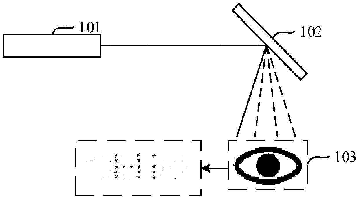
[0061] For ease of understanding, the basic principles of laser scanning imaging in existing near-eye display devices are firstly described. Such as figure 1 is shown schematically, figure 1 It includes: a laser light source 101 , a scanner 102 and a human retina 103 .

[0062] When displaying imaging, the laser light emitted by the laser light source is output by the scanner and acts on a certain pixel position to realize the scanning of the pixel position. Controlled by the scanner, the laser beam moves to the next pixel position to scan. In other words, th...


PUM


Abstract

The embodiment of the application discloses an image source module, a waveguide, a near-eye display system and a control method thereof. An eye tracking module monitors the rotation angle of the eyesof a user in real time so as to determine an area corresponding to the field of view of the user on an image, and generates and sends an adjustment signal to the image source module and / or the waveguide to adjust an emergent beam. The adjusted beam can only display the image in the field of view of the user during imaging display, so that the interference of the displayed content to the user can be reduced while the power consumption of the system is reduced.

Description

technical field [0001] This application relates to the technical field of laser scanning display, in particular to an image source module, a waveguide, a near-eye display system and a control method thereof. Background technique [0002] Nowadays, with the rapid development of display technologies such as augmented reality (Augmented Reality, AR) and virtual reality (Virtual Reality, VR), near-eye display devices such as head-mounted displays (Head-Mounted Display, HMD) have also become an important part of the display industry. hotspots. [0003] Existing near-eye display devices can use laser scanning to display images with a larger field of view, but in some scenarios, images with a larger field of view will cause some problems, for example: if a user wears an AR device while walking , an image with a large field of view will block the user's sight too much, which may bring safety hazards; another example: in the process of object analysis through AR equipment, an image ...

Claims


Application Information

Patent Timeline
Patent Type & Authority Applications(China)
IPC IPC(8): G02B27/01G02B27/00G02B26/10
Inventor 姚长呈
Owner CHENGDU IDEALSEE TECH
Why Eureka
Try Eureka