Polaroid attaching device and polaroid attaching method

A technology for attaching polarizers and polarizers, which is applied in optics, nonlinear optics, instruments, etc., can solve problems such as polarizer drop and adsorption, and achieve the effect of increasing the probability of blocking inspection and reducing poor quality

Inactive Publication Date: 2019-06-07
SHENZHEN CHINA STAR OPTOELECTRONICS SEMICON DISPLAY TECH CO LTD
View PDF9 Cites 2 Cited by
  • Summary
  • Abstract
  • Description
  • Claims
  • Application Information

AI Technical Summary

Problems solved by technology

Since there is no detection mechanism in the working process of the polarizer attaching machine, there may be a risk of the machine absorbing multiple polarizers, resulting in subsequent polarizers being attached to the LCD panel and falling off

Method used


Image

  • Polaroid attaching device and polaroid attaching method
  • Polaroid attaching device and polaroid attaching method

Examples


Embodiment Construction

[0033] In order to further illustrate the technical means adopted by the present invention and its effects, the following describes in detail in conjunction with preferred embodiments of the present invention and accompanying drawings.

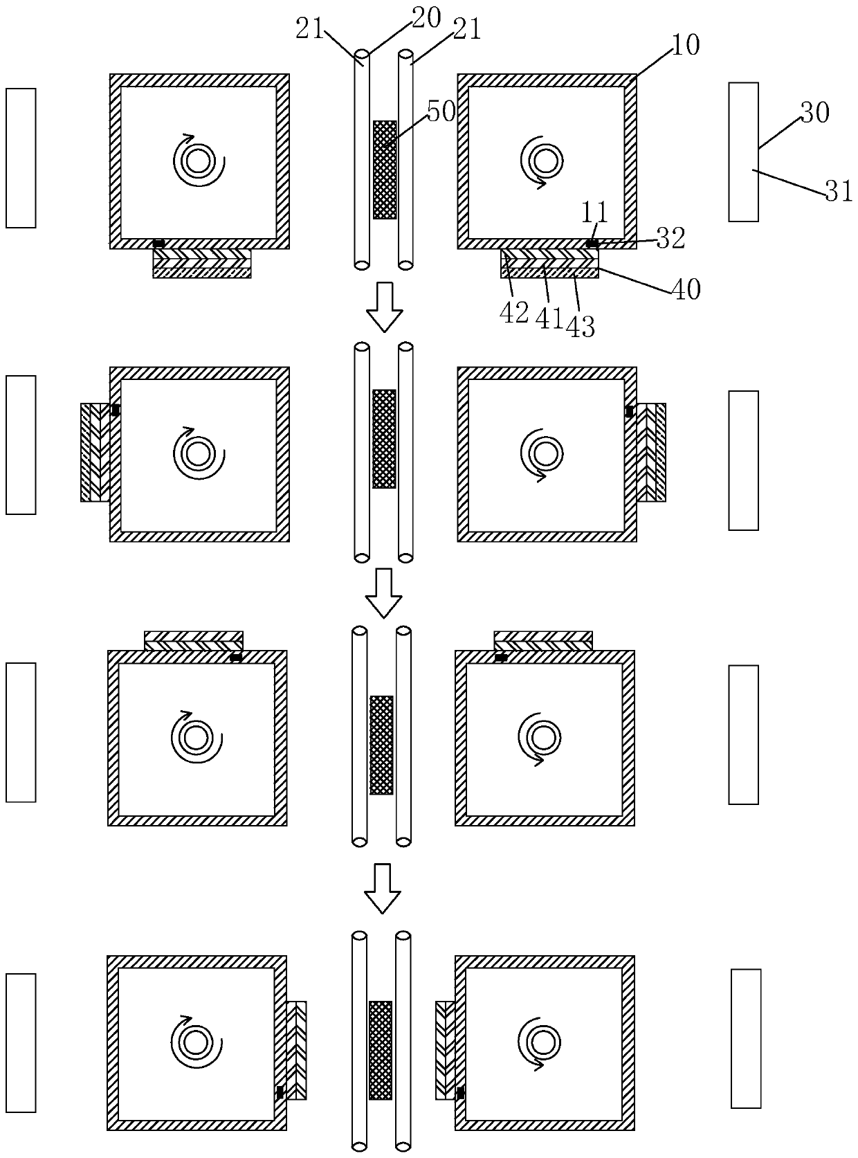
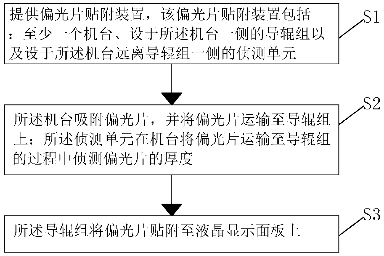
[0034] see figure 1 , the present invention provides a polarizer sticking device, comprising: at least one machine table 10, a guide roller set 20 arranged on one side of the machine table 10, and a guide roller set 20 arranged on the side of the machine table 10 away from the guide roller set 20 detection unit 30;

[0035] The machine 10 is used to absorb the polarizer 40, and transport the polarizer 40 to the guide roller set 20;

[0036] The guide roller set 20 is used to attach the polarizer 40 to the liquid crystal display panel 50;

[0037] The detection unit 30 is used for detecting the thickness of the polarizer 40 when the machine 10 transports the polarizer 40 to the guide roller set 20 .

[0038] It should be noted that, in the p...


PUM


Abstract

The invention provides a polaroid attaching device and a polaroid attaching method. The polaroid attaching device comprises at least one bench, guide roller set arranged at one side of the bench, anda detection unit arranged at one side, away from the guide roller set, of the bench. The bench is used for absorbing a polaroid and conveying the polaroid to the guide roller set. The guide roller setis used for absorbing the polaroid to a liquid crystal display panel. The detection unit is used for detecting the thickness of the polaroid during the process of conveying the polaroid to the guideroller set on the bench. Therefore, the number of the polaroids absorbed by the bench can be detected effectively, so that the stopping-checking probability of selecting multiple ones from the polaroids is increased and thus the poor quality phenomenon is reduced. According to the provided method, the number of the polaroids absorbed by the bench can be detected effectively; the stopping-checkingprobability of selecting multiple ones from the polaroids is increased; and the poor quality phenomenon is reduced.

Description

technical field [0001] The invention relates to the field of display technology, in particular to a polarizer attaching device and a polarizer attaching method. Background technique [0002] Thin Film Transistor (TFT) is the main driving element in current Liquid Crystal Display (LCD) and Active Matrix Organic Light-Emitting Diode (AMOLED). It is related to the display performance of the flat panel display device. [0003] Most of the liquid crystal displays currently on the market are backlight liquid crystal displays, which include a liquid crystal display panel and a backlight module. The working principle of the liquid crystal display panel is to pour liquid crystal molecules between the thin film transistor array substrate (ThinFilm Transistor Array Substrate, TFT Array Substrate) and the color filter (ColorFilter, CF) substrate, and apply pixel voltage on the two substrates respectively. and the common voltage, through the electric field formed between the pixel volt...

Claims


Application Information

Patent Timeline
IPC IPC(8): G02F1/13G02F1/1335
Inventor 刘宗秀
Owner SHENZHEN CHINA STAR OPTOELECTRONICS SEMICON DISPLAY TECH CO LTD
Why Eureka
Try Eureka