Direct-current outer rotor water fetching motor bracket and motor

A motor bracket and outer rotor technology, applied in the direction of the casing/cover/support, electromechanical devices, electrical components, etc., to achieve the effects of reducing operating noise, reliable structure, and reducing friction damage

Pending Publication Date: 2021-04-30
合肥珺安机电设备有限公司
View PDF1 Cites 0 Cited by
  • Summary
  • Abstract
  • Description
  • Claims
  • Application Information

AI Technical Summary

Problems solved by technology

However, this structure has limitations. In the general processing technology of small and micro motors, in order to reduce the dynamic unbalance of the motor and reduce the vibration of the motor, the two key points, the clearance fit between the bearing and the shaft and the coaxiality between the bearings, should be adjusted. Ensure that the installation coaxiality of the two bearings is reduced during the assembly process of the motor. Therefore, a new rotor support structure is adopted to effectively reduce the increase in the bearing coaxiality caused by the installation during the installation process, thereby improving the installation level. product quality

Method used


Image

  • Direct-current outer rotor water fetching motor bracket and motor
  • Direct-current outer rotor water fetching motor bracket and motor
  • Direct-current outer rotor water fetching motor bracket and motor

Examples


Embodiment Construction

[0029] The following will clearly and completely describe the technical solutions in the embodiments of the present invention with reference to the accompanying drawings in the embodiments of the present invention. Obviously, the described embodiments are only some, not all, embodiments of the present invention. Based on the embodiments of the present invention, all other embodiments obtained by persons of ordinary skill in the art without creative efforts fall within the protection scope of the present invention.

[0030] In describing the present invention, it is to be understood that the terms "opening", "upper", "lower", "thickness", "top", "middle", "length", "inner", "surrounding" etc. Indicating orientation or positional relationship is only for the convenience of describing the present invention and simplifying the description, and does not indicate or imply that the components or elements referred to must have a specific orientation, be constructed and operated in a sp...


PUM


Abstract

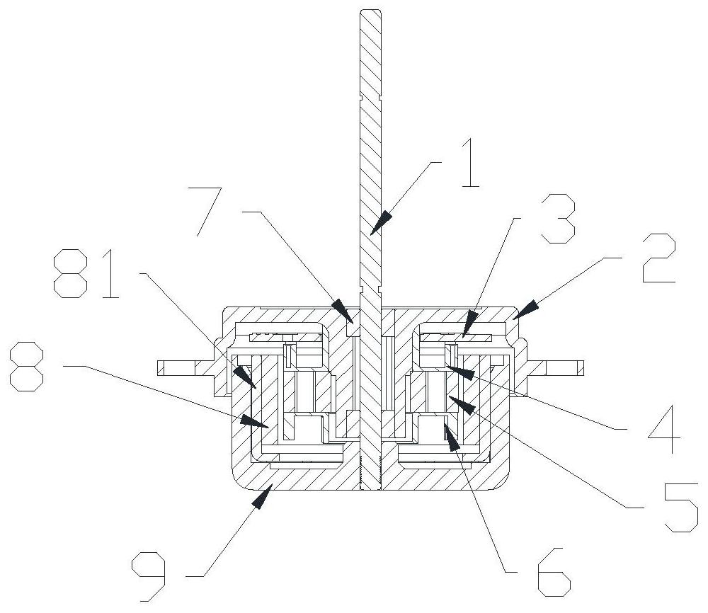
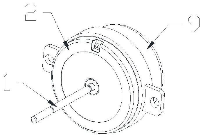
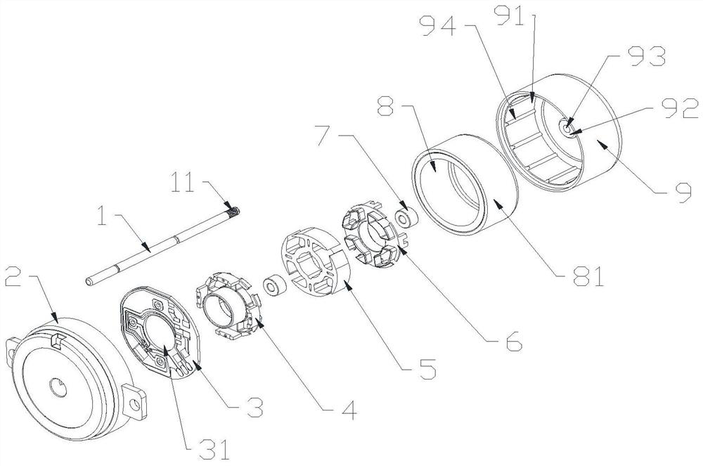
The invention disclose a direct-current outer rotor water fetching motor bracket and a motor. The direct-current outer rotor water fetching motor comprises a motor support, a support inner groove is formed in the motor support, an installation column is arranged in the support inner groove, an installation hole is formed in the installation column, a stress boss is arranged in the installation hole, and oil bearings are arranged at the two ends of the stress boss. The oil bearings are internally provided with motor rotating shafts together. A circuit board is arranged in the support inner groove, a stator lower insulation frame and a stator upper insulation frame are arranged on one side of the circuit board, a stator is arranged between the stator lower insulation frame and the stator upper insulation frame, annular magnetic rings are arranged on the outer sides of the stator lower insulation frame, the stator upper insulation frame and the stator, and a rotor iron shell is arranged on the outer sides of the annular magnetic rings. And a rotor rubber shell is arranged outside the rotor iron shell. The motor bracket is reliable in structure, capable of effectively reducing poor quality caused by large bearing coaxiality in the motor assembling process, high in stability, good in motor lubricating effect, capable of effectively reducing friction damage to a motor rotating shaft, good in rotating flatness and capable of reducing running noise.

Description

technical field [0001] The invention relates to the field of household electrical appliances, in particular to a bracket and a motor for a DC outer rotor water pumping motor. Background technique [0002] At present, many external rotor motors on the market use an oil-impregnated bearing to support the rotor. Since the rotating shaft has only one fulcrum, the concentricity of the rotor during rotation cannot be guaranteed, which will cause quality defects. At the same time, the oil-impregnated bearing has less oil content. After the oil bearing in the middle is worn or the oil storage is exhausted, it cannot provide continuous lubrication to the shaft, which will eventually lead to severe bearing wear. [0003] In the motor support structure provided by the patent publication number CN208424042U, lubricating oil is stored between two oil bearings, and the through-hole structure of the storage chamber is used to provide lubrication between the bearing and the rotating shaft w...

Claims


Application Information

Patent Timeline
Patent Type & Authority Applications(China)
IPC IPC(8): H02K1/27H02K1/18H02K5/00H02K7/08H02K5/16H02K3/34
CPCH02K1/187H02K1/2786H02K3/345H02K5/00H02K5/161H02K7/083
Inventor 魏彬彬
Owner 合肥珺安机电设备有限公司
Why Eureka
Try Eureka