
A multi-pass band-pass filter

A filter and microstrip line technology, which is applied in the field of multi-pass band-pass filters, can solve the problem that multi-pass band-pass filters cannot take into account size, loss, pass-band stop-band suppression, and pass-band selectivity center frequency bandwidth Adjustable and other issues, to achieve the effect of improving miniaturization and integration, low insertion loss, and simple structure

Active Publication Date: 2020-02-21
HUAZHONG UNIV OF SCI & TECH
View PDF7 Cites 0 Cited by
  • Summary
  • Abstract
  • Description
  • Claims
  • Application Information

AI Technical Summary

Problems solved by technology

[0007] Aiming at the defects of the prior art, the purpose of the present invention is to solve the problem that the existing multi-passband bandpass filter cannot take into account the size, loss, stopband suppression between passbands, passband selectivity, and adjustable center frequency bandwidth. technical problem

Method used


Image

  • A multi-pass band-pass filter
  • A multi-pass band-pass filter
  • A multi-pass band-pass filter

Examples


Embodiment Construction

[0034] In order to make the object, technical solution and advantages of the present invention clearer, the present invention will be further described in detail below in conjunction with the accompanying drawings and embodiments. It should be understood that the specific embodiments described here are only used to explain the present invention, not to limit the present invention. In addition, the technical features involved in the various embodiments of the present invention described below can be combined with each other as long as they do not constitute a conflict with each other.

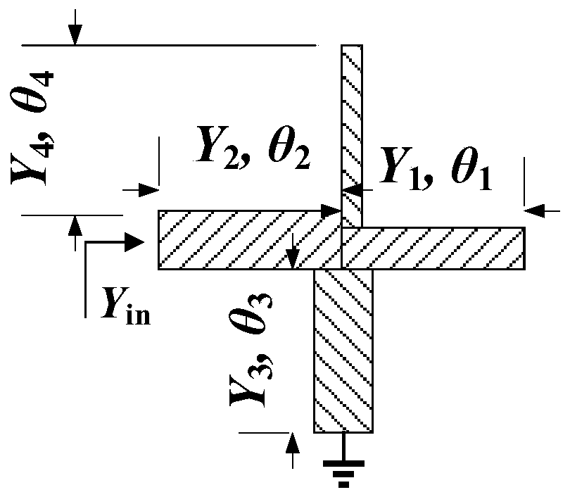
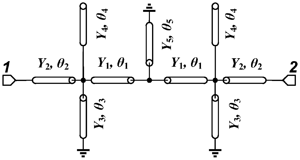
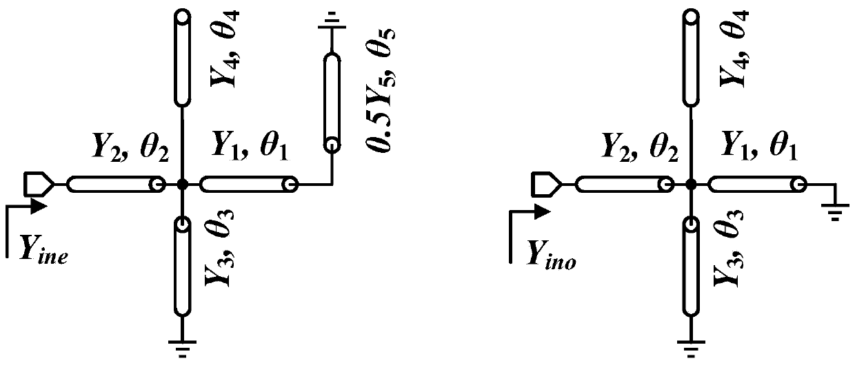
[0035] The present invention proposes a non-equal-width cross-connected resonator. A novel multi-mode resonator is formed by connecting two non-equal-width cross-connected resonators and adding a short-circuited microstrip line in the middle. The resonator produces multiple passbands with adjustable center frequencies and bandwidths. With a simple structure, the size is reduced, the insertion lo...


PUM


Abstract

The invention discloses a multi-pass bandpass filter. The multi-pass bandpass filter comprises a multimode resonator formed by two cross-shaped resonators and a short-circuited microstrip line; one end of the short-circuited microstrip line is grounded and in a short circuit state, the other end of the short-circuited microstrip line is connected with one ends of first microstrip lines of the twocross-shaped resonators; the other ends of the first microstrip lines of the two cross-shaped resonators are connected with one ends of second microstrip lines, one ends of third microstrip lines andone ends of fourth microstrip lines of the two cross-shaped resonators; the other end of the third microstrip lines of the two cross-shaped resonators are grounded and in a short circuit state; the other ends of the fourth microstrip lines of the two cross-shaped resonators are in an open circuit state; the other end of the second microstrip line of one cross-shaped resonator is taken as the inputend of the multimode resonator, and the other end of the second microstrip line of the other cross-shaped resonator is taken as the output end of the multimode resonator. The multi-pass bandpass filter employs a single resonator to achieve the multi-pass bandpass filter, so that the multi-pass bandpass filter has wide broad research significances and practical values.

Description

technical field [0001] The invention belongs to the field of band-pass filters, and more specifically relates to a multi-pass band-pass filter. Background technique [0002] With the rapid development of the communication industry, microwave radio frequency circuits and systems have attracted more and more attention from scientific researchers. As an important part of the radio frequency circuit, passive filters play a key role in filtering, so more passive filters of different frequency bands are applied to people's daily life, including WLAN, GPRS, Bluetooth, WAP, WiMAX, GPS and LTE etc. This makes our life more convenient and rich, but also increases the requirements for the miniaturization, integration, and high reliability of filters. However, the spectrum resources we can use are limited. In order to solve the contradiction between the increasing spectrum demand and the spectrum resource limit, the single passband filter can no longer meet the needs of wireless commu...

Claims


Application Information

Patent Timeline
Patent Type & Authority Patents(China)
IPC IPC(8): H01P1/20H01P1/203
Inventor 毕晓君王露华
Owner HUAZHONG UNIV OF SCI & TECH
Learn More