An operational amplification circuit capable of adjusting the reference voltage value
A technology of operational amplifier circuit and reference voltage, which is applied in the direction of amplifier combination and improved amplifier to reduce temperature/power supply voltage changes, etc. It can solve the problem of non-adjustable reference voltage and achieve low cost, high reliability and simple circuit structure.
- Summary
- Abstract
- Description
- Claims
- Application Information
AI Technical Summary
Problems solved by technology
Method used
Image

Examples
Embodiment 1
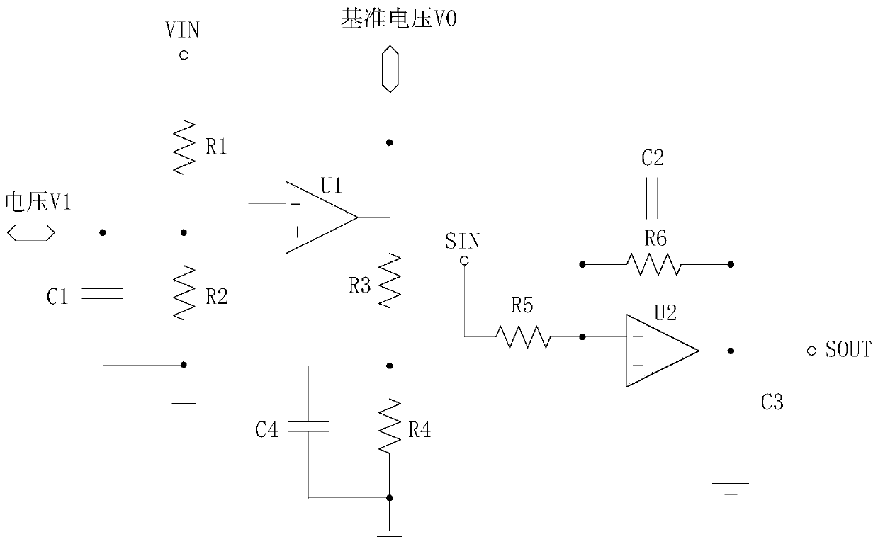
[0026] The operational amplifier circuit with adjustable reference voltage value described in Embodiment 1 of the present invention, such as figure 1 As shown, it includes: a reference voltage adjustment circuit and a sampling signal amplification circuit. The reference voltage adjustment circuit includes a power input terminal VIN. The sampling signal amplification circuit includes a signal input terminal SIN and a signal output terminal SOUT. The reference voltage adjustment circuit is connected to the sampling signal amplification circuit. The reference voltage adjustment circuit adjusts the voltage input from the power input terminal VIN and then inputs it as a reference voltage to the sampling signal amplification circuit; the sampling signal amplification circuit amplifies the sampling signal input from the signal input terminal SIN and outputs it to the signal output terminal SOUT .
[0027] optional, such as figure 1 As shown, the reference voltage adjustment circuit ...
Embodiment 2
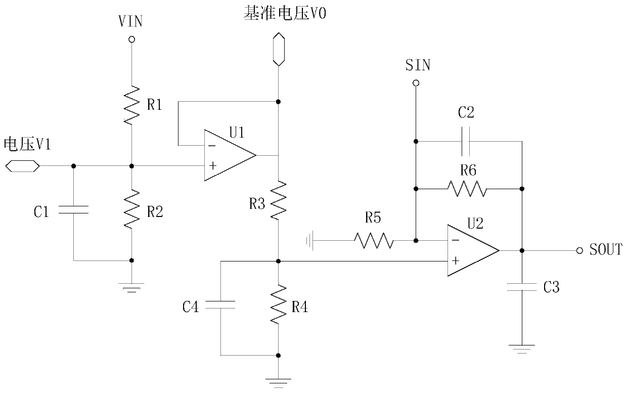
[0037] The circuit structure and principle of this embodiment are basically the same as those of Embodiment 1. Refer to Embodiment 1 for relevant points. The difference is that the sampling signal is input into the second operational amplifier U2 in a different way, such as figure 2 As shown, the sampling signal amplifying circuit includes: a third resistor R3, a fourth resistor R4, a fifth resistor R5, a sixth resistor R6, a seventh resistor R7, a second capacitor C2, a third capacitor C3 and a second operational amplifier U2, The output terminal of the first operational amplifier U1 is connected to the non-inverting input terminal of the second operational amplifier U2 through the third resistor R3, the non-inverting input terminal of the second operational amplifier U2 is grounded through the fourth resistor R4, and the second operational amplifier U2 is grounded through the fourth resistor R4. The negative phase input terminal of the amplifier U2 is respectively connected ...
Embodiment 3
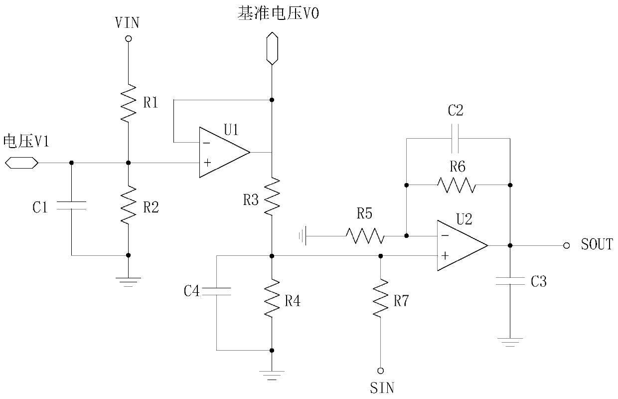
[0040] The circuit structure and principle of this embodiment are basically the same as those of Embodiment 1. Refer to Embodiment 1 for relevant points. The difference is that the sampling signal is input into the second operational amplifier U2 in a different way, such as image 3 As shown, the sampling signal amplifying circuit includes: a third resistor R3, a fourth resistor R4, a fifth resistor R5, a sixth resistor R6, a seventh resistor R7, a second capacitor C2, a third capacitor C3 and a second operational amplifier U2, The output terminal of the first operational amplifier U1 is connected to the non-inverting input terminal of the second operational amplifier U2 through the third resistor R3, the non-inverting input terminal of the second operational amplifier U2 is grounded through the fourth resistor R4, and the second operational amplifier U2 is grounded through the fourth resistor R4. The positive-phase input terminal of the amplifier U2 is connected to the signal ...
PUM
 Abstract
Description
Claims
Application Information
 - R&D
- Intellectual Property
- Life Sciences
- Materials
- Tech Scout
- Unparalleled Data Quality
- Higher Quality Content
- 60% Fewer Hallucinations
Browse by: Latest US Patents, China's latest patents, Technical Efficacy Thesaurus, Application Domain, Technology Topic, Popular Technical Reports.
© 2025 PatSnap. All rights reserved.Legal|Privacy policy|Modern Slavery Act Transparency Statement|Sitemap|About US| Contact US: help@patsnap.com