An automatic slicer for biomedical research experiments

A biomedical and experimental technology, applied in the field of biomedical research, can solve the problem of small cutting range of the cutter, and achieve the effect of large cutting range and widening cutting width.

Active Publication Date: 2020-12-08
湖南省弘华中药饮片有限公司
View PDF9 Cites 0 Cited by
  • Summary
  • Abstract
  • Description
  • Claims
  • Application Information

AI Technical Summary

Problems solved by technology

However, when the invention is sliced, the cutting range of the cutter is relatively small

Method used


Image

  • An automatic slicer for biomedical research experiments
  • An automatic slicer for biomedical research experiments
  • An automatic slicer for biomedical research experiments

Examples


specific Embodiment approach 1

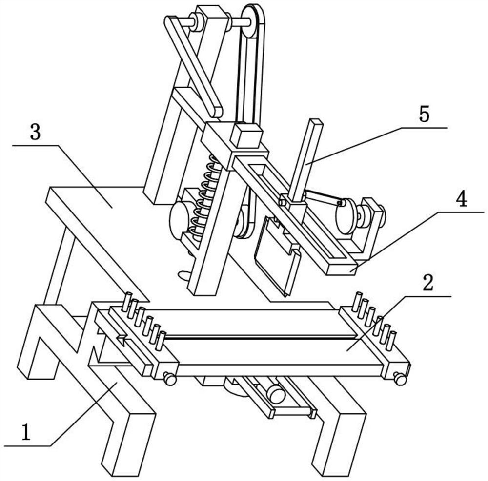
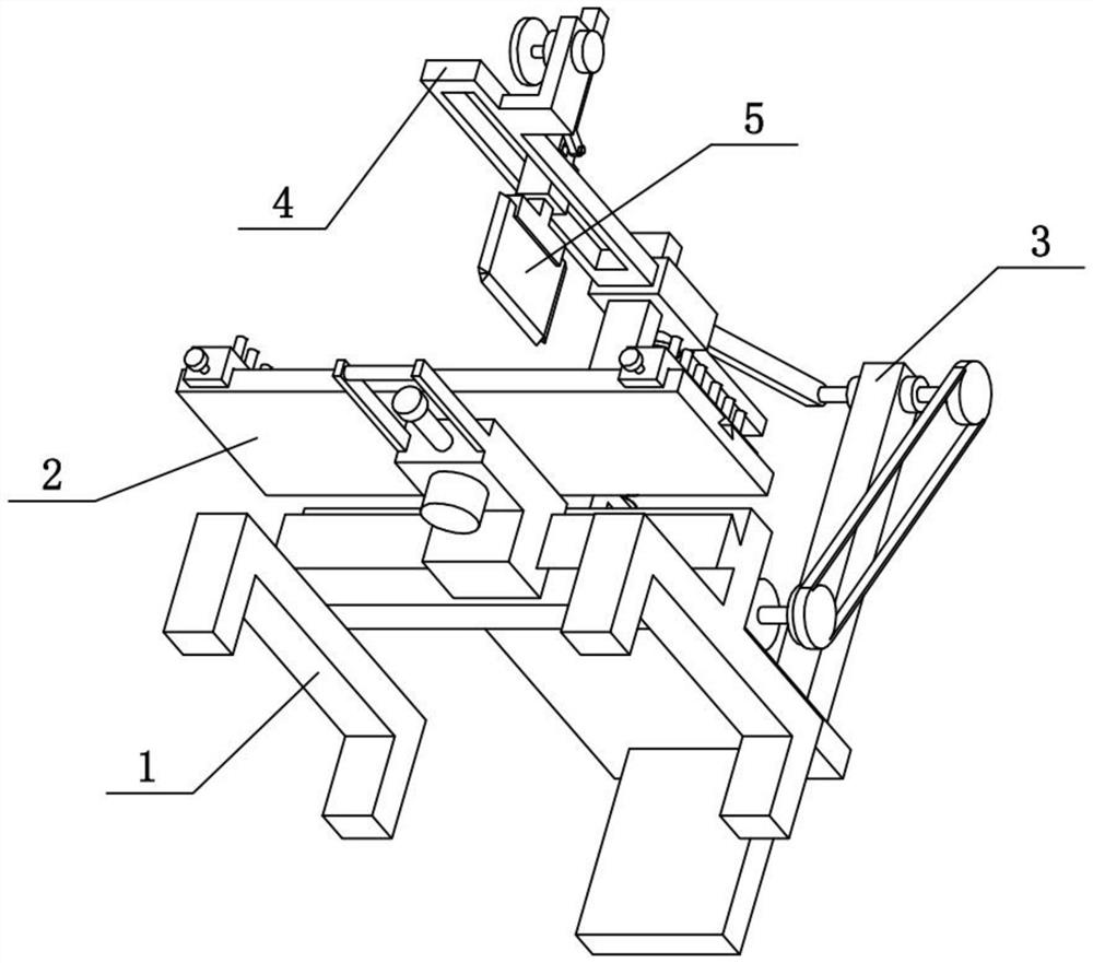
[0031] Combine below Figure 1-10 To illustrate this embodiment, the present invention relates to the field of biomedical research, more specifically, an automatic slicer for biomedical research experiments, including a support frame 1, a cutting table 2, a rear seat mechanism 3, a lifting cutting frame 4 and a cutting knife Component 5, the upper end of the cutting table 2 in the present invention is used to fix the medical materials for research, when the lifting cutting frame 4 moves down, the medicinal materials on the cutting table 2 can be sliced, and the cutting table 2 can be cut with the axis of the central axis 2-6 Rotate for the axis, and can move left and right, adjust the position of the medicinal material to slice the medicinal material, and the lower end, front end and rear end of the cutter 5-4 are all provided with blades, and the cutter 5-4 can also reciprocate back and forth during the downward movement Move, strengthen the cutting width of cutting knife 5-4...

specific Embodiment approach 2

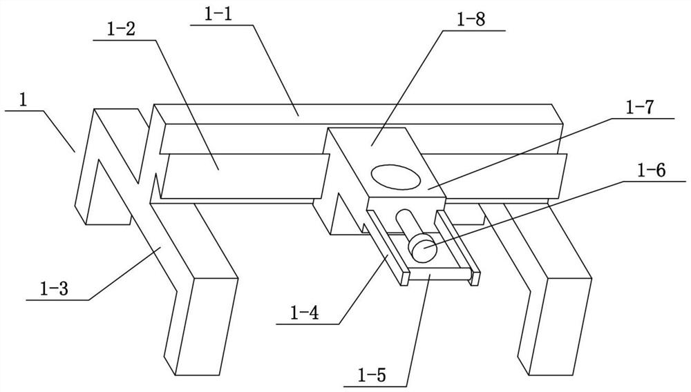
[0034] Combine below Figure 1-10To illustrate this embodiment, the support frame 1 includes a beam 1-1, a trapezoidal slide rail 1-2, a door frame 1-3, a fastening screw I1-6, a swivel seat 1-7 and a slider 1-8, The front end of the beam 1-1 is provided with a trapezoidal slide rail 1-2, and the slide block 1-8 is slidably connected to the trapezoidal slide rail 1-2, and the front end of the slide block 1-8 is fixedly connected with a plug-in swivel seat 1-7, and the plug-in swivel The front end of seat 1-7 is threadedly connected with fastening screw I1-6, and the left and right ends of crossbeam 1-1 are all fixedly connected with gantry 1-3. The two gantry frames 1-3 play the role of supporting the beam 1-1, and the slide block 1-8 can slide leftward or rightward on the trapezoidal slide rail 1-2.

specific Embodiment approach 3

[0036] Combine below Figure 1-10 To illustrate this embodiment, the cutting table 2 includes a flat plate 2-1, a trapezoidal slideway 2-2, a pin 2-3, a translation plate 2-4, a fastening screw II2-5 and a central axis 2-6, and the flat plate 2 The upper end of -1 is provided with a trapezoidal slideway 2-2, and the center of the lower end of the flat plate 2-1 is fixedly connected with a central shaft 2-6, and the central shaft 2-6 is inserted into the swivel seat 1-7 with clearance fit, and the fastening screw I1 -6 is placed on the central axis 2-6, and there are two translation plates 2-4 left and right, and the two translation plates 2-4 are respectively slidably connected to the left and right ends of the trapezoidal slideway 2-2, and the two translation plates 2- The upper end of 4 is provided with a plurality of pins 2-3, and the front ends of the two translation plates 2-4 are screwed with fastening screws II2-5, and the two fastening screws II2-5 are all supported on...


PUM


Abstract

The invention relates to the field of biological medicine study, in particular to an automatic slicing device for biological medicine study tests. The automatic slicing device comprises a supporting frame, a cutting table, a rear base mechanism, a lifting cutting frame and a cutter assembly. The upper end of the cutting table is used for fixing medicinal materials for study. The lifting cutting frame can slice the medicinal materials on the cutting table when moving downwards. The cutting table can rotate with the axis of a center shaft as a shaft and can move left and right, so that the position of the medicinal materials is adjusted, and the medicinal materials are sliced. Blades are arranged at the lower end, the front end and the rear end of the cutter. The cutter can move front and back in a reciprocating manner in the downward moving process, the cutting width of the cutter is enlarged, and the cutting range of the cutter is wider. The cutting table is connected to the supportingframe in a rotating manner. The rear base mechanism is fixedly connected to the rear end of the supporting frame. The lifting cutting frame is connected to the rear base mechanism in a sliding manner. The cutter assembly is connected to the lifting cutting frame in a sliding manner. The cutter assembly is located above the cutting table.

Description

technical field [0001] The invention relates to the field of biomedical research, in particular to an automatic slicer for biomedical research experiments. Background technique [0002] The application number is CN201811340022.7, an automatic slicer for medicinal materials. The invention provides an automatic slicer for medicinal materials, which includes a frame body and an electric control box fixed on the side of the frame body. The upper end of the frame body is fixedly connected to the bottom plate . A power output module is fixedly installed inside, and the power output module is connected to the material cutting module. The upper part of the material cutting module is correspondingly provided with a pressing module fixed on the top of the bottom plate, and the lower part is correspondingly provided with a pressing module fixed on the bottom plate. The outer skin receiving module at the lower end, the lower part of the cutting module is also provided with a cutting mod...

Claims


Application Information

Patent Timeline
Patent Type & Authority Patents(China)
IPC IPC(8): B26D1/06B26D5/06B26D7/20
Inventor 杨秦其他发明人请求不公开姓名
Owner 湖南省弘华中药饮片有限公司
Why Eureka
Try Eureka