Reversing mechanism of pneumatic conveying system, and pneumatic conveying system

A reversing mechanism and pneumatic conveying technology, applied in conveyors, transportation and packaging, conveying bulk materials, etc., can solve the problems of complex equipment structure, noise of intercepting device, and low equipment utilization rate.

Pending Publication Date: 2019-06-11
上海速地工业科技有限公司
View PDF1 Cites 2 Cited by
  • Summary
  • Abstract
  • Description
  • Claims
  • Application Information

AI Technical Summary

Problems solved by technology

In order to provide two airflows in opposite directions, it is usually necessary to configure two fans for the conveying pipeline. The investment cost of the equipment is relatively high, and during the conveying process, one fan is always running and the other is on standby, so the utilization rate of the equipment is not high.
[0003] Chinese patent CN102900866B discloses an air-to-air valve. Although the air-to-air valve can also adjust the airflow direction flowing through the material delivery pipeline, in the scheme disclosed in thi

Method used


Image

  • Reversing mechanism of pneumatic conveying system, and pneumatic conveying system
  • Reversing mechanism of pneumatic conveying system, and pneumatic conveying system
  • Reversing mechanism of pneumatic conveying system, and pneumatic conveying system

Examples


Embodiment Construction

[0045] Exemplary embodiments of the present invention are described below with reference to the accompanying drawings. It should be understood that these specific descriptions are only used to teach those skilled in the art how to implement the present invention, but are not intended to exhaust all possible ways of the present invention, nor are they intended to limit the scope of the present invention.

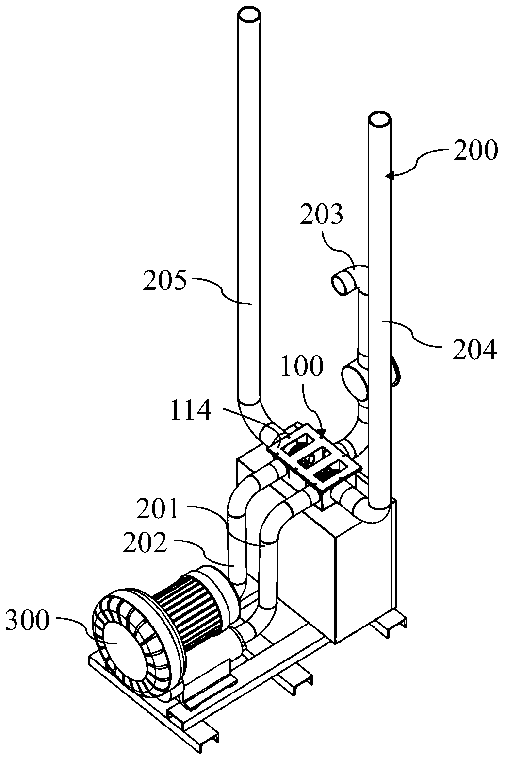
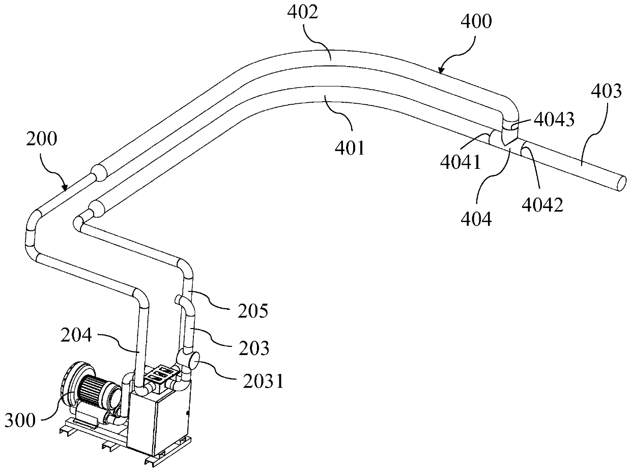
[0046] refer to figure 1 and figure 2 , the pneumatic conveying system according to the present invention includes a reversing mechanism 100 , an airflow regulating pipe 200 , a material conveying pipe 400 and a fan 300 . Wherein, the airflow regulating duct 200 includes an air outlet pipe 201 , an air inlet pipe 202 , a ventilation pipe 203 , an air suction pipe 204 and an air blow pipe 205 . One end of the air outlet pipe 201 and the air inlet pipe 202 are connected to the fan 300, and the other end is connected to the reversing mechanism 100 to provide air flow to the r...


PUM


Abstract

The invention provides a reversing mechanism of a pneumatic conveying system, and the pneumatic conveying system. An inner cavity of a shell of the reversing mechanism is divided into three cavities through a first partition board (111) and a second partition board (112), the first partition board (111) is provided with a first inner cavity opening (126), and the second partition board (112) is provided with a second inner cavity opening (127); the outer wall of the shell is provided with an air outlet (121), an air inlet (122), a ventilation opening (123), an air suction port (124) and an airblowing port (125); the reversing mechanism (100) further comprises a reversing execution assembly capable of blocking the air suction port (124) and the second inner cavity opening (127) at the sametime, so that a material conveying pipeline (400) can obtain positive pressure; and meanwhile, the reversing execution assembly can block the air blowing port (125) and the first inner cavity opening(126) at the same time, so that the material conveying pipeline (400) obtains negative pressure. According to the reversing mechanism, the flowing direction of airflow in the reversing mechanism is adjusted as needed, so that bidirectional conveying of materials is achieved.

Description

technical field [0001] The invention relates to the field of pneumatic conveying, in particular to a pneumatic conveying system capable of forwardly and reversely conveying materials and a reversing mechanism of the pneumatic conveying system. Background technique [0002] In the application of pneumatic pipeline transportation, it is usually required that a certain transportation pipeline can have both the function of forward transportation and the function of reverse transportation. direction movement. In order to provide two airflows in opposite directions, it is usually necessary to configure two fans for the conveying pipeline. The input cost of the equipment is high, and during the conveying process, one fan is always running and the other is on standby, so the utilization rate of the equipment is not high. [0003] Chinese patent CN102900866B discloses an air-to-air valve. Although the air-to-air valve can also adjust the airflow direction flowing through the materia...

Claims


Application Information

Patent Timeline
IPC IPC(8): B65G53/16B65G53/34
Inventor 缪岑汪学顺陈强
Owner 上海速地工业科技有限公司
Why Eureka
Try Eureka