Detecting device and method of frost heave stress

A stress detection and frost heave technology, applied in measuring devices, on-site foundation soil surveys, instruments, etc., can solve the problem that the quality control of infrastructure construction in permafrost areas is difficult to ensure, the frost heave stress detection of permafrost is difficult, and the construction site is difficult to detect. Due to complex geological conditions and other problems, the acquisition method is simple and direct, the installation position and direction are not limited, and the sampling points are many.

Active Publication Date: 2019-06-11
HARBIN INST OF TECH
View PDF8 Cites 3 Cited by
  • Summary
  • Abstract
  • Description
  • Claims
  • Application Information

AI Technical Summary

Problems solved by technology

[0005] The object of the present invention is to provide a frost heaving stress detection device and its detection method to solve the problem of the difficulty of detecting the frost heave stress of frozen soil due to the complex geological conditions at the construction site, low efficiency, and poor accuracy. Difficult to Guarantee Problems in Construction Quality Control

Method used


Image

  • Detecting device and method of frost heave stress
  • Detecting device and method of frost heave stress
  • Detecting device and method of frost heave stress

Examples


specific Embodiment approach 1

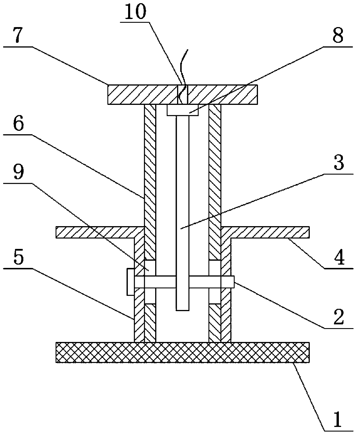
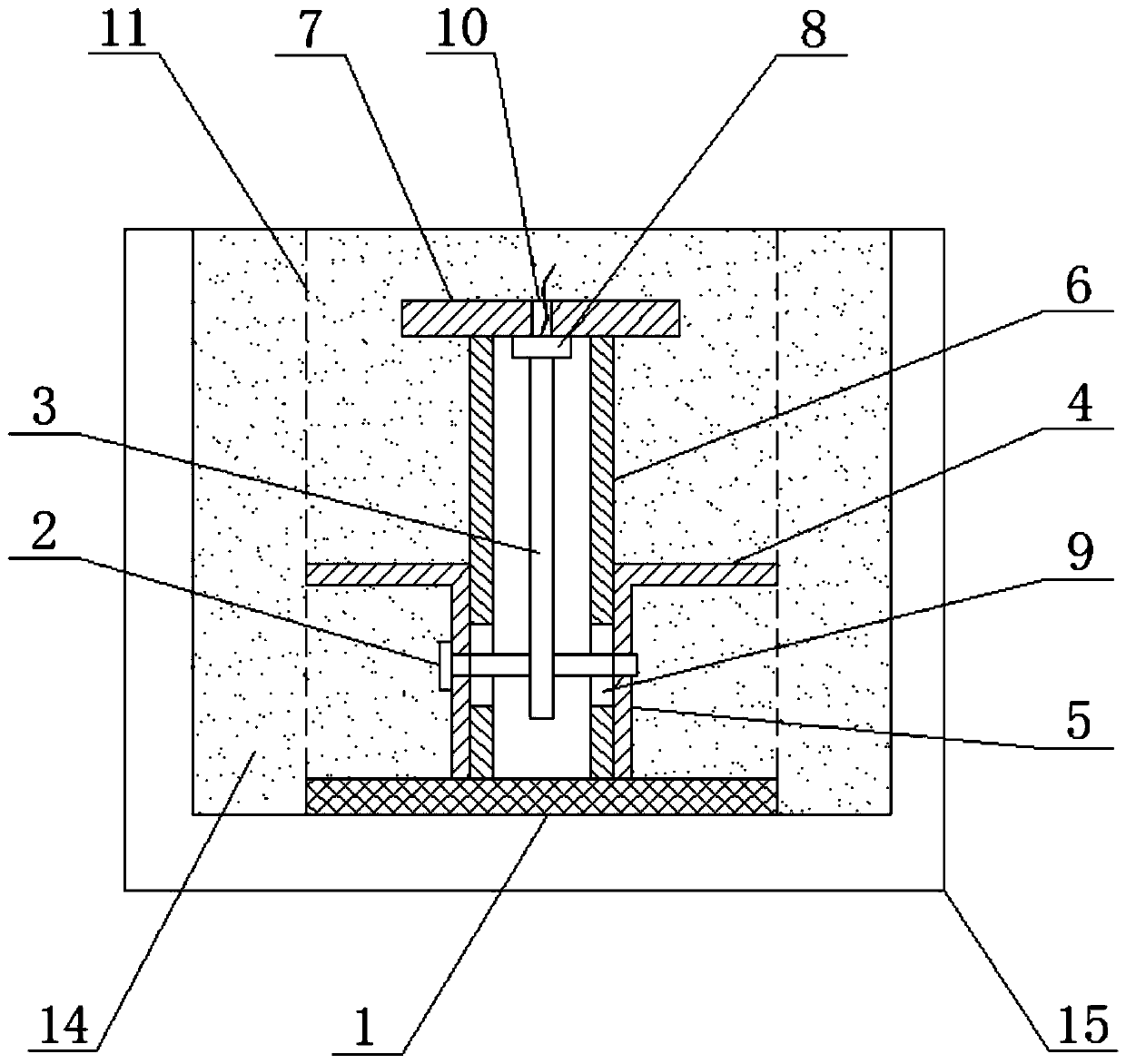
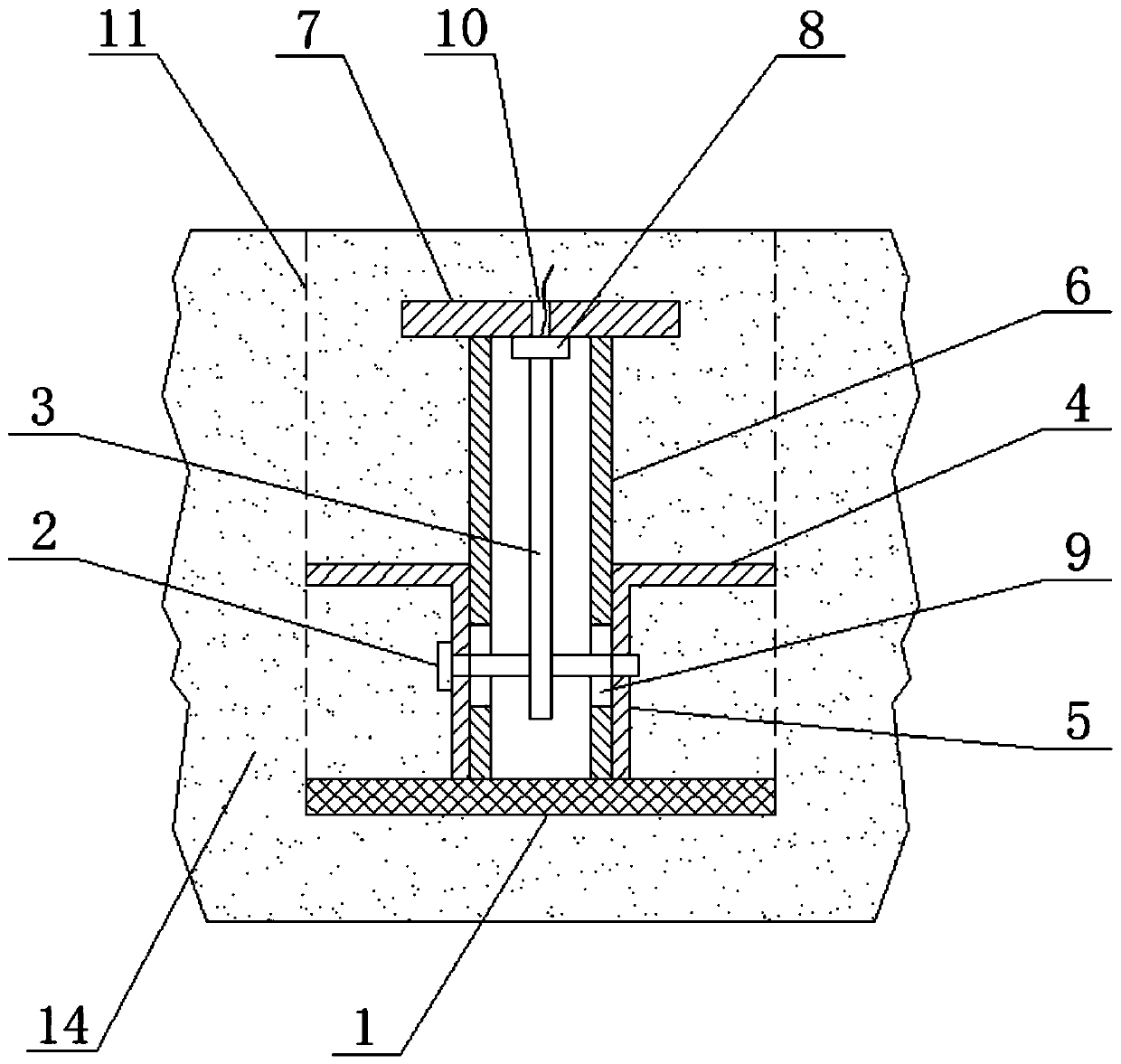
[0032] Specific implementation mode one: combine figure 1 , figure 2 and image 3 Describe this embodiment, this embodiment includes chassis 1, connecting rod 2, motion rod 3, anchor disc 4, sliding sleeve 5, sleeve 6, upper cover 7 and pressure sensor 8, sliding sleeve 5 is sleeved outside sleeve 6 and The two are slidingly matched, the anchor plate 4 is fixedly set outside the sliding sleeve 5, the connecting rod 2 passes through the sliding sleeve 5 and the sleeve 6 in the radial direction of the sliding sleeve 5, and the side wall of the sleeve 6 is processed with a matching connecting rod 2 The long hole 9 that moves up and down along its axial direction, the lower end of the sleeve 6 is fixedly connected to the chassis 1, the upper end of the sleeve 6 is fixedly connected with the upper cover 7, the pressure sensor 8 is located in the sleeve 6 and is arranged on the upper On the cover 7, the upper end of the moving rod 3 is set towards the measuring head of the pressu...

specific Embodiment approach 2

[0037] Specific implementation mode two: combination figure 1 , figure 2 and image 3 Describe this implementation mode, this implementation mode includes the following content:

[0038] According to the type of frozen soil in the test area, determine the number of measuring points in the test area and the distribution position of each measuring point, and determine the number of installed frost heave stress detection devices and the location of each frost heave stress detection device according to the distribution of each measurement point The frost heaving stress data of the frost heaving layer where each measuring point is located is obtained by detecting the frost heaving stress detection device, and the overall situation of the frost heaving stress in the test area is obtained according to the frost heaving stress data fed back by each measuring point.

[0039] According to the geological survey report, the test area is divided. The division principle is based on the n...

specific Embodiment approach 3

[0047] Specific implementation mode three: this implementation mode is a further limitation of specific implementation mode one or two, the frost heaving sensitive permafrost area is the concentration area of ​​measuring points in the test area, and the corresponding number is selected according to the number of measuring points in the frost heaving sensitive permafrost area The frost heaving stress detection device, the present invention combined with the prototype to carry out multiple tests according to the geological survey situation, in the frost heaving sensitive permafrost area plane horizontal and vertical intervals of 50cm ~ 100cm arrangement of measuring points is the best setting range, according to the unit per square meter Set 1 to 4 measuring points in the area, and arrange the measuring points at a horizontal and vertical interval of 200cm to 400cm in the plane of the frost heave non-sensitive area, which can be set according to 1 to 4 measuring points in a unit a...


PUM


Abstract

The invention discloses a detecting device and method of frost heave stress. In the engineering construction of a cold area, due to the fact that geological conditions are complex in a construction site, detecting difficulty of the frost heave stress of frozen earth is large, and the efficiency is low, nature determining can only be conducted, or indirect calculating is conducted to obtain, quantitative data of the frost heave stress can not be directly obtained. According to the detecting device of the frost heave stress, a sliding sleeve sleeves outside a sleeve, the sliding sleeve and the sleeve are slidably matched, an anchor disc fixedly sleeves outside the sliding sleeve, a connecting rod penetrates through the sliding sleeve and the sleeve in the radial direction of the sliding sleeve in sequence, a long hole is machined on the side wall of the sleeve, the long hole is matched with the connecting rod and moves in the axial direction of the connecting rod up and down, the lower end of the sleeve is fixedly connected to a base disc, an upper cover is arranged at the upper end of the sleeve, a pressure sensor is located in the sleeve and arranged on the upper cover, the upper end of a moving rod contacts with a probe of the pressure sensor, and the lower end of the moving rod is arranged on the connecting rod. The detecting device and method of the frost heave stress are used for detecting the frost heave stress of the frozen earth.

Description

technical field [0001] The invention belongs to the technical field of civil engineering, and in particular relates to a frost heave stress detection device and a detection method thereof. Background technique [0002] Frost heaving force is the force generated by the migration of water into the frozen soil and the phase change when the temperature drops below the freezing temperature of the soil during the formation of frozen soil. When the temperature continues or continues to decrease, most of the liquid water in the soil turns into solid water, and the phase change gradually slows until it disappears. In this process, the liquid water in the soil solidifies and fills the gaps between the soil particles in the form of ice. When the volume expansion of the water phase change in the soil is enough to cause the relative displacement between the soil particles, the soil mass is caused. frost heave.. Three conditions must be met at the same time for frost heave to occur in s...

Claims


Application Information

Patent Timeline
Patent Type & Authority Applications(China)
IPC IPC(8): E02D1/00G01N25/14
Inventor 杨英姿徐定杰徐扬
Owner HARBIN INST OF TECH
Why Eureka
Try Eureka