An environment-friendly energy saving and emission reduction system

An energy-saving, emission-reducing, and environmentally-friendly technology that is applied to combustion types, lighting and heating equipment, and incinerators. Efficient effect of slag discharge and waste incineration

Active Publication Date: 2020-01-10
浙江绿创新拓建筑规划设计有限公司
View PDF5 Cites 0 Cited by
  • Summary
  • Abstract
  • Description
  • Claims
  • Application Information

AI Technical Summary

Problems solved by technology

The garbage in the existing incinerator is directly placed in the incineration room, which on the one hand causes accumulation, and on the other hand, some incompletely crushed garbage will seriously affect the incineration efficiency, fuel consumption and slag discharge rate during incineration.
[0005] On the other hand, the existing crushing devices for rubbish generally shred the rubbish through the interaction of two rollers with hobbing teeth. Since the distance between the rollers remains unchanged, it is not suitable for The crushing of garbage that is too large or too small in size adopts a shredding method. The crushing of garbage can only achieve preliminary crushing, and the degree of crushing needs to be further improved, and the degree of crushing of garbage will affect the subsequent process. Sufficiency of incineration, large-volume garbage is difficult to be fully incinerated and incinerated is more difficult, which leads to a large amount of slag discharge, increases incineration time, and consumes more energy

Method used


Image

  • An environment-friendly energy saving and emission reduction system
  • An environment-friendly energy saving and emission reduction system
  • An environment-friendly energy saving and emission reduction system

Examples


Embodiment 1

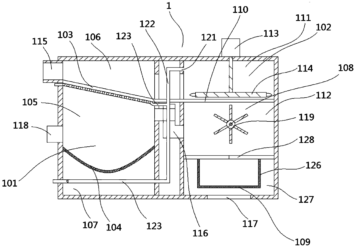
[0034] An environment-friendly energy-saving and emission-reduction system, including an incinerator 1, and a garbage crushing device 2, which is arranged before the incinerator 1, so that the garbage can be pulverized and ground before entering the incinerator 1, so as to ensure that the subsequent incinerator 1 sufficiency of incineration.

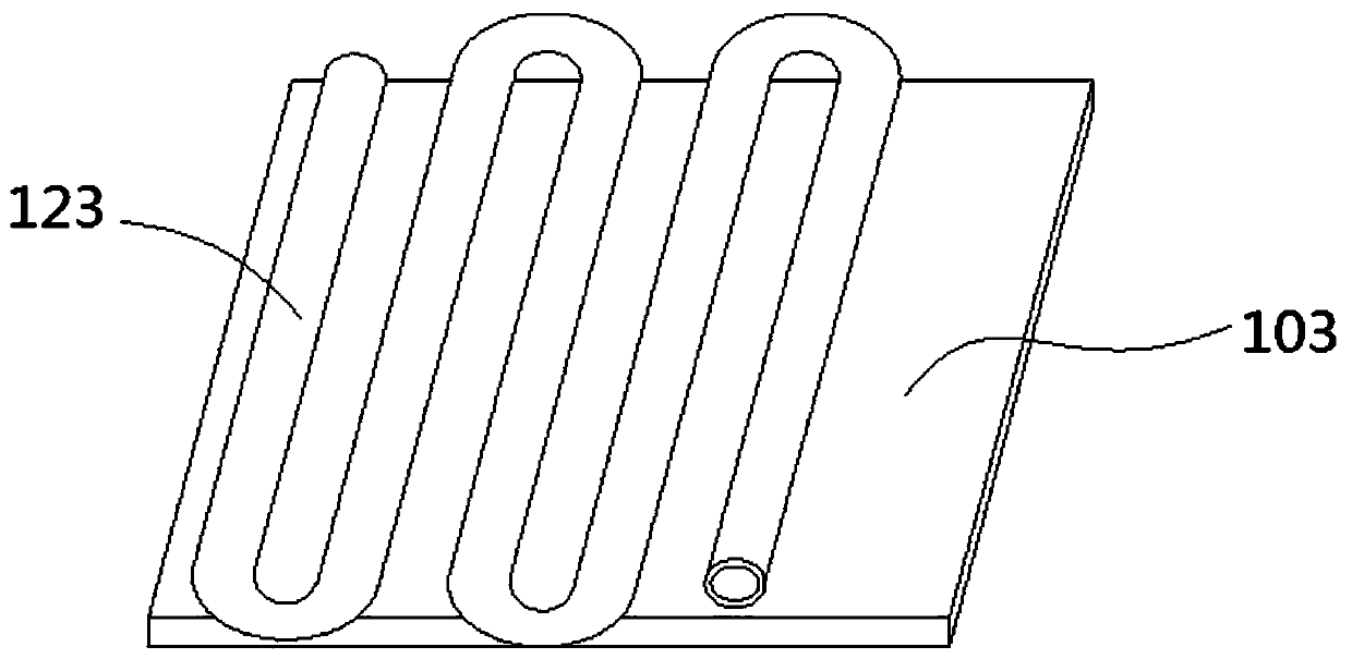
[0035] Such as figure 1 As shown, the incinerator 1 in the system has a special structural design, which includes a pretreatment chamber 101 and an incineration chamber 102. The first filter plate 103 and The arc-shaped aluminum plate 104 sunken downwards, the first filter plate 103 and the arc-shaped aluminum plate 104 separate the pretreatment chamber 101 into a large particle garbage chamber 106, a dust garbage chamber 105 and a water storage chamber 107 successively from top to bottom; Incineration chamber 102 Including the upper incineration chamber 108 and the lower fuel chamber 109, a horizontally arranged second filter plate 110...


PUM


Abstract

The invention relates to an energy conservation and emission reduction system, and discloses an environment-friendly type energy conservation and emission reduction system. An incinerator of the environment-friendly type energy conservation and emission reduction system comprises a pretreatment chamber and an incineration chamber. The pretreatment chamber is sequentially divided into a large-particle trash chamber, a dust trash chamber and a water storage chamber from top to bottom. The incineration chamber comprises an incineration cavity and a fuel cavity. The incineration cavity is dividedinto a large particle incineration cavity and a dust incineration cavity. A stirring and smashing paddle is arranged in the incineration cavity. An induced draft fan communicating with the dust trashchamber and the dust incineration cavity is arranged on the side wall of the dust trash chamber. A trash smashing device comprises a roller and crushing bodies distributed on the left side and the right side of the roller correspondingly. Each crushing body comprises a crushing block used in cooperation with the outer side wall of the roller for conducting trash crushing. The width of a trash crushing cavity is gradually decreased from top to bottom. According to the environment-friendly type energy conservation and emission reduction system, by means of the structural design of the incinerator and the trash smashing device, the incineration efficiency and the incineration sufficiency can be increased to a great extent, the incineration time can be sufficiently shortened, the fuel consumption and the slag discharge amount can be reduced, and the effects of energy conservation and emission reduction can be achieved.

Description

technical field [0001] The invention relates to an energy saving and emission reduction system, in particular to an environment-friendly energy saving and emission reduction system. Background technique [0002] The solid waste generated in human daily life and production, commonly known as garbage, has a large amount of discharge, complex and diverse components, and is polluting, resourceful, and social, and requires harmless, resourceful, reduction, and socialized treatment , If not handled properly, it will pollute the environment, affect environmental sanitation, waste resources, undermine production and living safety, and disrupt social harmony. [0003] At present, the municipal solid waste treatment methods widely used at home and abroad mainly include sanitary landfill, high-temperature composting and incineration, etc. The proportions of these three main waste treatment methods vary due to factors such as geographical environment, waste composition, and economic dev...

Claims


Application Information

Patent Timeline
Patent Type & Authority Patents(China)
IPC IPC(8): F23G5/02F23G5/033F23G5/44F23G7/00F23J15/06
Inventor 刘莎
Owner 浙江绿创新拓建筑规划设计有限公司
Why Eureka
Try Eureka