Pressure adjusting device for laparoscopic suction device

A laparoscopic suction and pressure adjustment technology, which is applied in the fields of suction equipment, medical science, surgery, etc., can solve the problems that clinicians cannot install in a timely and convenient manner, time-consuming disassembly and installation, and prolonged operation time, so as to save the need for equipment replacement , Guarantee safety, reasonable design effect

Inactive Publication Date: 2019-06-14
孟凡龙
View PDF11 Cites 4 Cited by
  • Summary
  • Abstract
  • Description
  • Claims
  • Application Information

AI Technical Summary

Problems solved by technology

[0004] The patent with publication number CN204972433U discloses a laparoscopic aspirator, which includes a liquid suction part and a liquid discharge part. The liquid pipe, the liquid discharge part is provided with an air inlet channel communicating with the air inlet, the liquid discharge pipe has a liquid discharge channel, and the liquid suction part includes a cavity filled with fillers. The device does not absorb liquid while absorbing liquid. The gas in the artificial air cavity ensures the surgical field of view, but the operation of the device requires manual operation by the doctor, and manpower cannot guarantee that there will be no negative pressure;
[0005] The patent with the publication number CN207575530U discloses a detachable laparoscopic suction device, which is hollow tubular in shape and consists of upper, middle and lower sections. The upper section is used to connect with conventional suction tubes and negative pressure devices; the lower section is for suction The main body of the device is used to extend into the patient's body. The middle section is composed of two arc-shaped tubes and a connecting tube, which can be disassembled and assembled at will to make the operation more convenient, but the device may attract the tissues inside the abdominal cavity structure, and disassembly and installation are time-consuming, and clinicians cannot install it in a timely and convenient manner, resulting in prolonged operation time and greatly increasing the risk of surgery for patients

Method used


Image

  • Pressure adjusting device for laparoscopic suction device
  • Pressure adjusting device for laparoscopic suction device
  • Pressure adjusting device for laparoscopic suction device

Examples


Embodiment Construction

[0037] In order to make the purpose, technical solutions and advantages of the embodiments of the present invention clearer, the technical solutions in the embodiments of the present invention will be clearly and completely described below in conjunction with the drawings in the embodiments of the present invention. Obviously, the described embodiments It is a part of embodiments of the present invention, but not all embodiments. Based on the embodiments of the present invention, all other embodiments obtained by persons of ordinary skill in the art without creative efforts fall within the protection scope of the present invention.

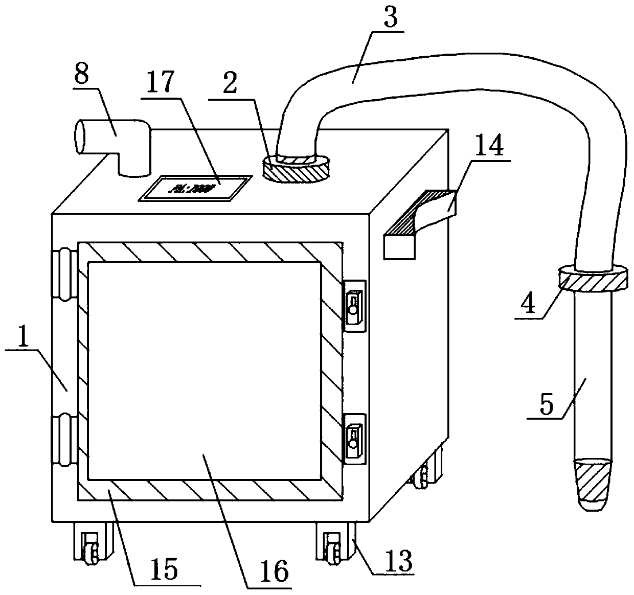
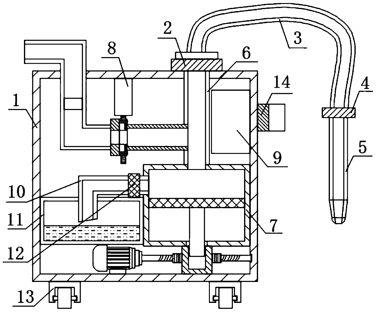
[0038] Refer to attached figure 1 and 2A pressure regulating device for a laparoscopic suction device provided by an embodiment of the present invention includes a case 1, a telescopic hose 3 installed on the upper end of the case 1 through a hose joint 2, and a laparoscopic suction device installed at the other end of the telescopic hose 3. Dev...


PUM


Abstract

The invention relates to the technical field of medical instruments, in particular to a pressure adjusting device for a laparoscopic suction device. The pressure adjusting device comprises a casing, atelescopic hose installed at the upper end of the casing through a hose joint and the laparoscopic suction device installed at the other end of the telescopic hose. The lower end of the hose joint extends into the inner cavity of the casing and is connected to a negative pressure generating assembly through a first connecting pipe, and a pressure regulating device body is mounted on the side wallof the first connecting pipe. The pressure adjusting device overcomes the shortcomings in the prior art, is reasonable in design and compact in structure, and adjusts the negative pressure accordingto the pressure change inside the laparoscopic suction device through the PLC intelligent control. At the same time, the pipeline structure convenient to stretch is combined to stretch the device intothe abdominal cavity of a patient for a surgery, and the safety of the patient is effectively ensured.

Description

technical field [0001] The invention relates to the technical field of medical instruments, in particular to a pressure regulating device for a laparoscopic aspirator. Background technique [0002] Laparoscopic surgery is an operation completed by modern high-tech medical technology with advanced equipment principles such as electronics and optics. It is a cross-generational progress of traditional laparotomy. Minimally invasive surgery has become an important direction in the development of modern medicine. During the laparoscopic operation, due to fat liquefaction and small blood vessel damage caused by cutting and separating tissues, bleeding and exudate will occur, which requires a laparoscopic suction device to suck it out. [0003] The laparoscopic aspirator is used to suck out the contents of bleeding, exudate, pus, and thoracic viscera during the operation, so as to make the operation clear and reduce the chance of contamination. The principle of the aspirator is v...

Claims


Application Information

Patent Timeline
Patent Type & Authority Applications(China)
IPC IPC(8): A61B17/00A61M1/00
Inventor 孟凡龙
Owner 孟凡龙
Why Eureka
Try Eureka