Bar cutting tool life prediction method

A technology of tool life and prediction method, applied in manufacturing tools, measuring/indicating equipment, metal processing equipment, etc., can solve problems such as inapplicability of bar shearing machines, achieve fast prediction speed, small prediction error, and prevent processing quality. Effect

Active Publication Date: 2019-06-14
CHONGQING UNIV
View PDF11 Cites 5 Cited by
  • Summary
  • Abstract
  • Description
  • Claims
  • Application Information

AI Technical Summary

Problems solved by technology

[0005] Existing tool life prediction methods need to rely on expensive automatic testing equipment, which is not suitable for bar shearing machines, and there is no life prediction method specifically for bar shearing tools in the prior art

Method used


Image

  • Bar cutting tool life prediction method
  • Bar cutting tool life prediction method
  • Bar cutting tool life prediction method

Examples


Embodiment Construction

[0032] The present invention will be further described below in conjunction with the accompanying drawings and specific embodiments, so that those skilled in the art can better understand the present invention and implement it, but the examples given are not intended to limit the present invention.

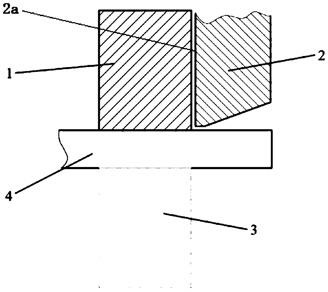
[0033] Such as figure 2 Shown is a diagram of the positional relationship between the movable knife and the fixed knife. The bar shearing tool includes a fixed knife 3 and a movable knife 2. When in use, the fixed knife 3 is fixedly installed below, and the bar 4 is pressed and fixed on the fixed knife 3 by the pressing device 1. The movable knife 2 is located on the bar. Above the material 4, the side 2a of the movable knife 2 faces the side where the fixed knife is located.

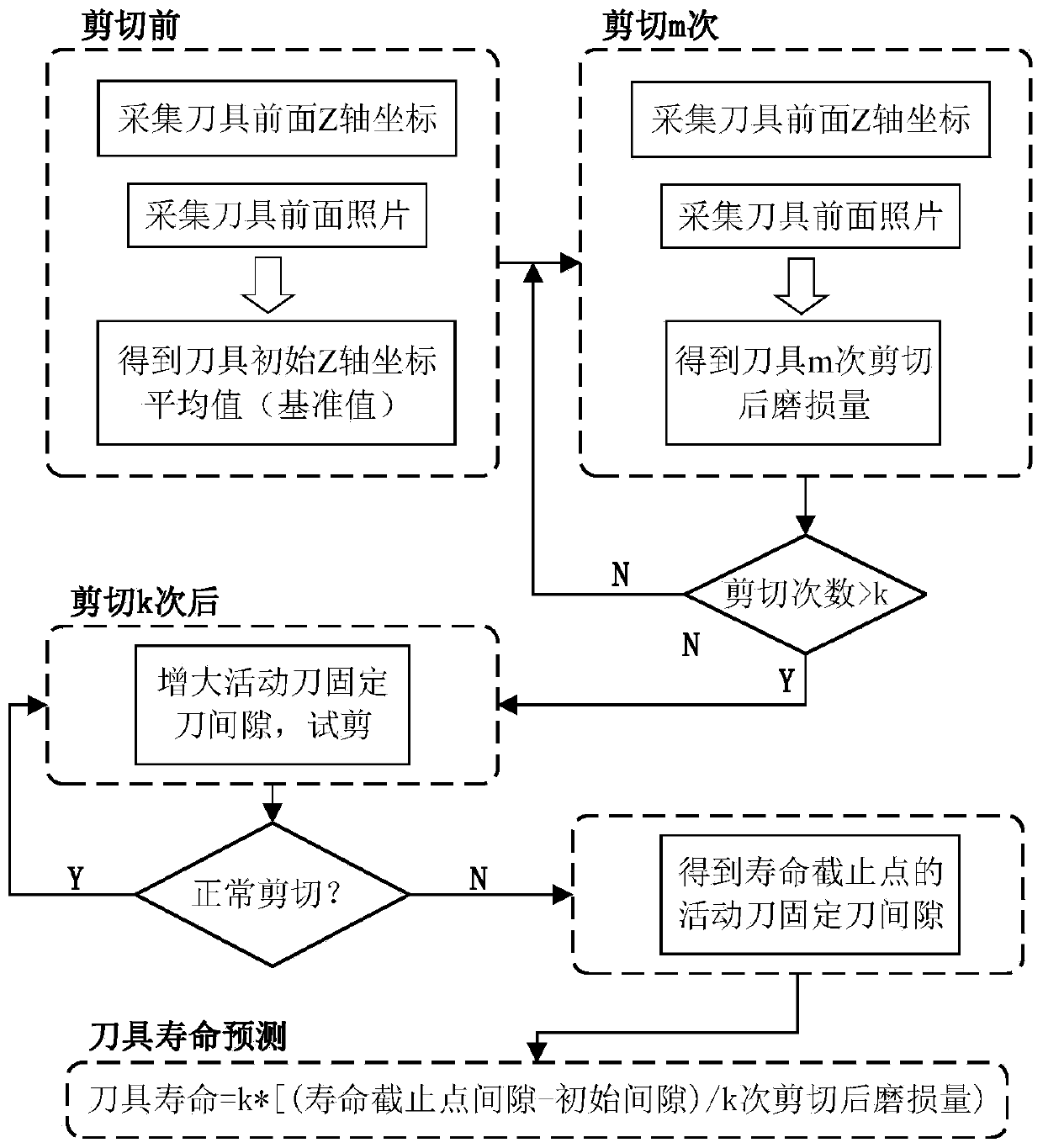
[0034] Such as figure 1 Shown is a flow chart of an embodiment of the method for predicting the life of a bar shearing tool in the present invention. The method for predicting the life of a bar shearing...


PUM


Abstract

The invention discloses a bar cutting tool life prediction method. The wearing capacity in each time of cutting is obtained by conducting quantitative detection on the wearing capacity of the side face of a movable tool, then the predicted life of a bar cutting tool is obtained according to the difference between the failure spacing distance and the initial spacing distance between a fixed tool and the movable tool, that is to say, the bar cutting tool life prediction method can achieve the technical purpose of obtaining the service life of the tool in the design stage, and the reliability ofthe cutting machine property is improved. Particularly, the bar cutting tool life prediction method has the following advantages that firstly, a full life test does not need to be conducted on the tool, and the characteristics of being low in economical cost, high in prediction speed and high in accuracy are achieved; secondly, a prediction result better conforms to an actual result, and the toollife prediction error is small; and thirdly, the tool life is predicted through the method, the tool can be replaced in advance, the condition that the blank machining quality is influenced due to thefact that the tool is damaged is prevented, and the reliability of a bar cutting machine is improved.

Description

technical field [0001] The invention belongs to the technical field of measuring the state of a cutting tool, in particular to a method for predicting the life of a bar shearing tool. Background technique [0002] In mechanical processing, the process of processing any form (pipe, bar or profile) material into the required geometric size is called blanking. The blanking is the first process of mechanical processing. Only the raw materials are separated into individual blanks. to proceed to the next step. Because of its low economic cost, high efficiency, and low consumption, bar shears are widely used before heating and forging processes. [0003] Due to the high ductility of stainless steel, severe irregular plastic deformation is prone to occur during the shearing process, and it scratches the shearing blade and the blade surface, which aggravates the wear of the blade. In extreme cases, it may even cause stress concentration at the blade, resulting in chipping of the bl...

Claims


Application Information

Patent Timeline
Patent Type & Authority Applications(China)
IPC IPC(8): B23Q17/09
Inventor 王时龙董建鹏周杰杨波易力力陈航
Owner CHONGQING UNIV
Why Eureka
Try Eureka