Clamping device for bench worker with omnibearing rotation function

A technology of rotating function and clamping device, applied in the field of machinery, can solve the problems of the influence of different operators, reduce the work efficiency of operators, and be inconvenient to use, and achieve the effect of convenient movement and placement of the clamping device

Active Publication Date: 2019-06-14
JILIN TEACHERS INST OF ENG & TECH
View PDF10 Cites 12 Cited by
  • Summary
  • Abstract
  • Description
  • Claims
  • Application Information

AI Technical Summary

Problems solved by technology

[0003] However, most of the worktables used by fitters are fixed. After the workpiece is clamped, the operator can only operate in one direction of the workpiece. When operating other parts of the workpiece, the workpiece needs to be unloaded again. Installation and clamping will increase the labor intensity of the operator and reduce the work efficiency of the operator. At the same time, the height of each operator is different, which will affect the operation of different operators, which is inconvenient to use. Moreover, the existing fitter work platform The moving effect is poor and the flexibility is low. In view of the above situation, we propose a clamping device for fitters with a full range of rotation functions

Method used


Image

  • Clamping device for bench worker with omnibearing rotation function
  • Clamping device for bench worker with omnibearing rotation function
  • Clamping device for bench worker with omnibearing rotation function

Examples


Embodiment Construction

[0019] The following will clearly and completely describe the technical solutions in the embodiments of the present invention with reference to the accompanying drawings in the embodiments of the present invention. Obviously, the described embodiments are only some, not all, embodiments of the present invention.

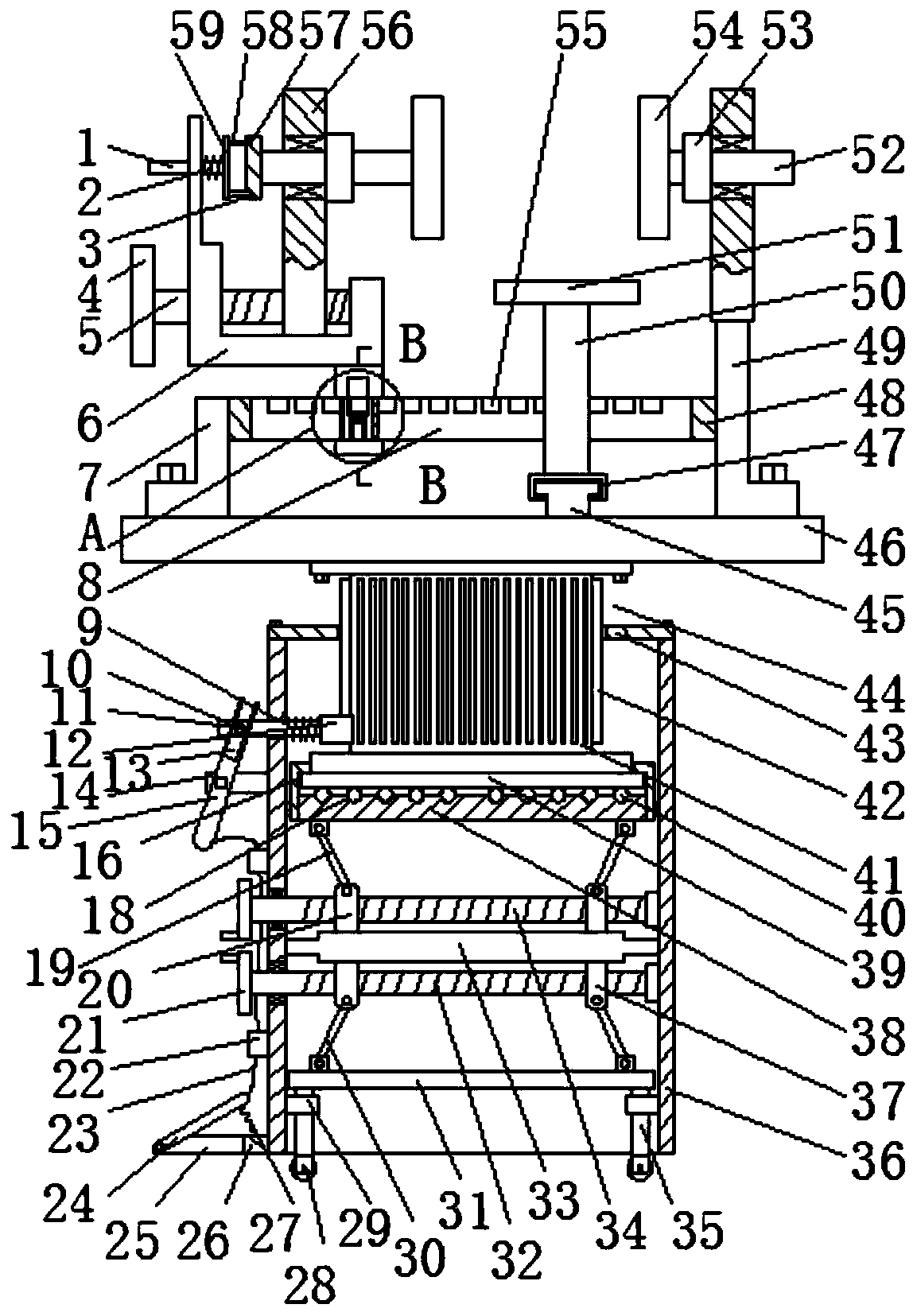
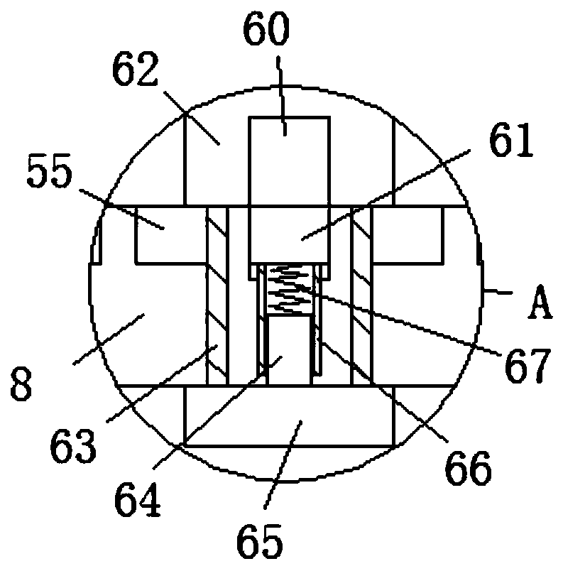
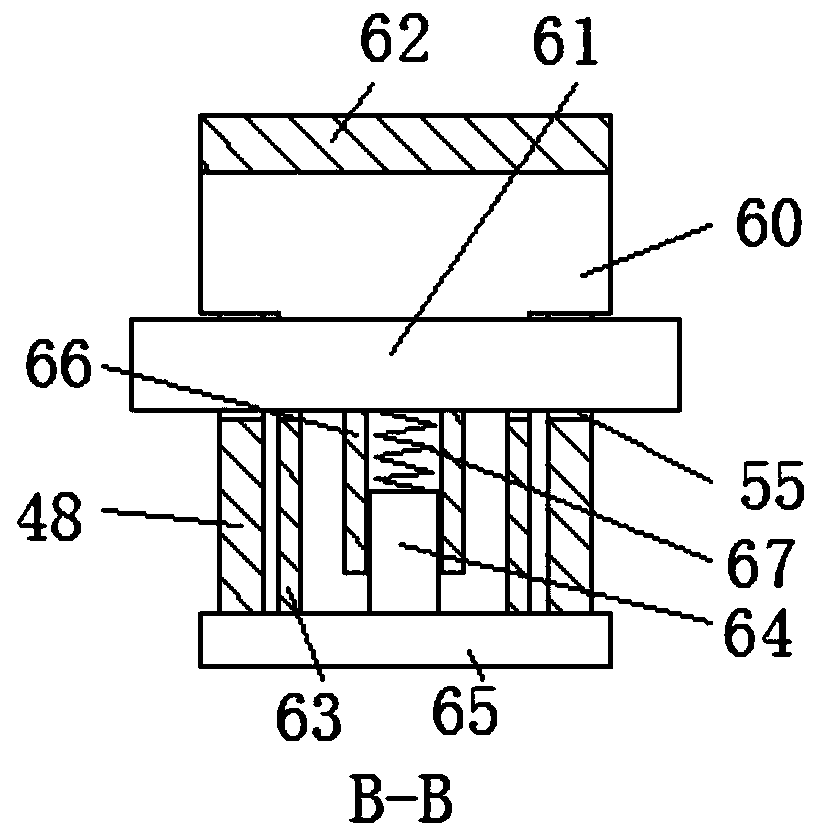
[0020] refer to Figure 1-5 , a clamping device for a fitter with a full range of rotation functions, including a housing 36, the inner middle part of the housing 36 is rotatably mounted with a second threaded rod 32 below the third threaded rod 34, and one end of the second threaded rod 32 runs through Outer shell 36, second threaded rod 32 is symmetrically threaded with two second threaded sliders 37 in opposite directions, the lower surface of second threaded sliders 37 is rotatably mounted with second connecting rod 30, two second The lower end of the connecting rod 30 is connected with the first moving plate 31 for common rotation, and three first guide rails 29...


PUM


Abstract

The invention relates to the technical field of machineries, in particular to a clamping device for a bench worker with an omnibearing rotation function. The clamping device for the bench worker withthe omnibearing rotation function comprises a shell, a third threaded rod is rotatably mounted in the middle of the inner side of the shell, a lifting column is mounted on the upper surface of a second limiting plate, a pedal is rotatably mounted in a mounting groove, a push groove connected with a push head is formed in one end of a rotating rod, and a limiting device is jointly mounted between aU-shaped plate and a left side rotary shaft. Compared with the prior art, according to the clamping device for the bench worker with the omnibearing rotation function, omnibearing rotation of a workpiece can be realized only by requiring clamping the workpiece at a time, various positions of the workpiece are presented in front of people, the working efficiency can be greatly improved, and the labor strength of operating personnel is reduced; meanwhile, the clamping speed of the workpiece is high, using is convenient, and safety and reliability are achieved; and the height of the clamping device can be adjusted and can meet the operating personnel with different heights for use, the clamping device can be further conveniently moved and placed, and the convenience of using is greatly improved.

Description

technical field [0001] The invention relates to the technical field of machinery, in particular to a clamping device for a fitter with omni-directional rotation function. Background technique [0002] With the continuous deepening of the transformation from traditional mechanical processing to modern mechanical processing, the types of mechanical processing are diversified. As one of the important types of processing, fitter processing is also constantly adapting to modern development, the precision of workpiece processing is also constantly improving, and the quality of workpiece processing is also constantly improving. [0003] However, most of the worktables used by fitters are fixed. After the workpiece is clamped, the operator can only operate in one direction of the workpiece. When operating other parts of the workpiece, the workpiece needs to be unloaded again. Installation and clamping will increase the labor intensity of the operator and reduce the work efficiency ...

Claims


Application Information

Patent Timeline
Patent Type & Authority Applications(China)
IPC IPC(8): B25B11/00
Inventor 王显峰郑作涛王玉双
Owner JILIN TEACHERS INST OF ENG & TECH
Why Eureka
Try Eureka