
Vehicle ramp device and automobile

A technology for ramps and vehicles, which is applied in the field of vehicle ramp devices and automobiles. It can solve the problems of poor durability and easy vibration and abnormal noise, and achieve the effects of long service life, optimized NVH function, and avoiding abnormal vibration and noise.

Active Publication Date: 2019-06-14
ZHEJIANG GEELY HLDG GRP CO LTD +2
View PDF7 Cites 1 Cited by
  • Summary
  • Abstract
  • Description
  • Claims
  • Application Information

AI Technical Summary

Problems solved by technology

[0004] The purpose of the present application is to provide a vehicle ramp device to solve the technical problems of easy shaking and abnormal noise and poor durability in the prior art

Method used


Image

  • Vehicle ramp device and automobile
  • Vehicle ramp device and automobile
  • Vehicle ramp device and automobile

Examples


Embodiment 1

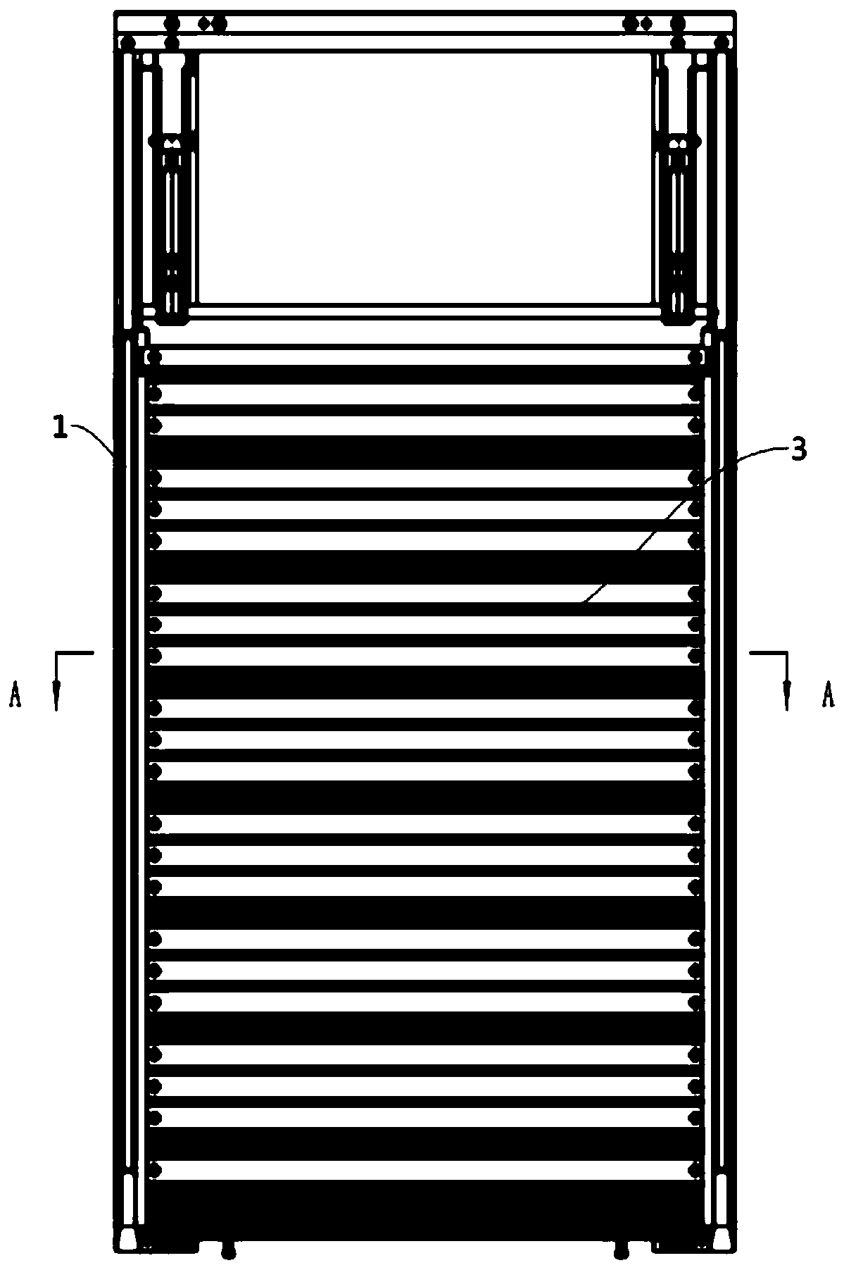
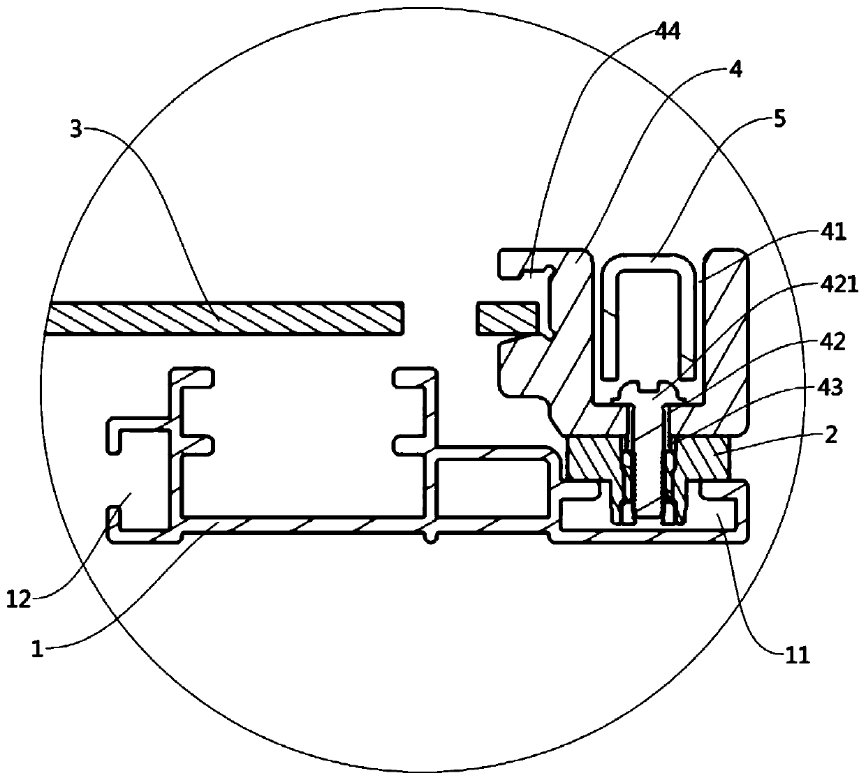
[0062] See figure 1 , figure 2 , image 3 , Figure 4 , Figure 5 , Image 6 , a vehicle ramp device, comprising a guide rail 1, a slide block 2 slidable on the guide rail 1, and a slope guide plate 3 connected to the slide block 2, the slide block 2 includes intersecting intermediate beams 21 and extending plate 22,

[0063] The extension board 22 includes at least one first extension board 221, the length of the single first extension board 221 is less than the length of the middle beam 21,

[0064] Wherein, the guide rail 1 is provided with a sliding groove 11 matched with the slider 2, and the sliding groove 11 includes two grooves intersecting each other, and the middle beam 21 and the first extension plate 221 can slide in the two grooves respectively.

[0065] In this application, the slider is composed of the intermediate beam and the extension plate which are intersected with each other, that is, an angle is formed between the intermediate beam and the extensio...

Embodiment 2

[0103] See image 3 , Figure 5 , Image 6 The surface of the second extension plate 222 is provided with a limiting groove 2223 communicating with the first connecting hole 2222 , and the connecting frame 4 is provided with a limiting protrusion 43 matching the limiting groove 2223 . A through hole or a through groove communicating with the second connecting hole 42 is formed on the limiting protrusion 43 . The fastener 421 passes through the first connecting hole 2222 , the through hole / groove and the second connecting hole 42 in order to connect the connecting frame 4 and the slider 2 together. All the other parts are the same as the first embodiment of the vehicle ramp device.

[0104] The setting of the limiting groove and the limiting protrusion can further limit the relative displacement between the slider and the connecting frame, reduce shaking and avoid generating noise. At the same time, it can also facilitate the calibration between the positions of the first c...


PUM


Abstract

The invention discloses a vehicle ramp device and an automobile, relates to the technical field of vehicle manufacturing, and solves the technical problems of easy vibration noise and poor durabilityin the prior art. In the vehicle ramp device of the invention, Each sliding block includes an intermediate beam and an extension plate which are arranged to intersect each other. Each extension plateincludes at least one first extension plate. The length of the single first extension plate is less than the length of the intermediate beam. Each guide rail is provided with a sliding groove matchingthe sliding block. Each sliding groove includes two groove channels which are arranged to intersect each other. Each intermediate beam and the corresponding first extension plates can respectively slide in the two corresponding groove channels. Therefore, a limit function of at least one direction of the sliding blocks is added to the vehicle ramp device, which reduces matching gaps between the sliding blocks and the guide rails to avoid the vibration noise, optimizes riding experience of passengers and reduces sliding resistance to improve the durability and increase the service life.

Description

technical field [0001] The present application relates to the technical field of vehicle manufacturing, in particular, to a vehicle ramp device and an automobile. Background technique [0002] In recent years, the production and sales of passenger cars have repeatedly hit new highs. In order to facilitate the boarding of some elderly people and children, especially those in wheelchairs, wheelchairs and their wheelchair boards, namely slope guides, will be arranged and installed on passenger cars. , but because the passenger car space is relatively small, the boarding board with folding and folding design will occupy the space of the passenger cabin and affect the appearance and space layout of the passenger cabin, so the boarding board with an integral design is better. It can reduce the space occupied by the passenger car. [0003] However, the existing one-piece design of the boarding board is a slope guide plate and a slide rail structure. Due to the lack of limit on the...

Claims


Application Information

Patent Timeline
Patent Type & Authority Applications(China)
IPC IPC(8): B60R3/00A61G3/06
CPCA61G3/06B60R3/00
Inventor 李志才林明世蔡伟坚张翔
Owner ZHEJIANG GEELY HLDG GRP CO LTD
Learn More