Magnetically driven crawler wheel capable of switching wheel state and crawler state

A crawler type, magnetic drive technology, applied in the direction of crawler vehicles, motor vehicles, electric components, etc., can solve the problems of vehicle power transmission, conversion efficiency, weak obstacle crossing ability, poor wheel grip performance, etc., to improve practicability and economy, increase the ground contact area, and improve the effect of driving speed

Active Publication Date: 2019-06-14
NANJING INST OF TECH
View PDF5 Cites 13 Cited by
  • Summary
  • Abstract
  • Description
  • Claims
  • Application Information

AI Technical Summary

Problems solved by technology

The main disadvantages of the wheeled driving mechanism are: because the wheels are in point or line contact with the ground, the grip performance of the wheels is poor, and they do not have the ability to prevent subsidence; because the ability of the round wheels to cross the vertical wall is proportional to the size of the wheel diameter , so its off-road capability is limited by the height limit of the wheel body
Although the existing technology can expand the diameter of the wheel to about 2.5 meters, its huge wheel body takes up too much car body space. The bigger problem is that a wheel with a diameter of 2.5 meters occupies a lot of space. The effective space of the car body is huge, and the required steering space greatly reduces the effective space

Method used


Image

  • Magnetically driven crawler wheel capable of switching wheel state and crawler state
  • Magnetically driven crawler wheel capable of switching wheel state and crawler state
  • Magnetically driven crawler wheel capable of switching wheel state and crawler state

Examples


Embodiment Construction

[0028] In order to make the technical means, creative features, goals and effects achieved by the present invention easy to understand, the present invention will be further described below in conjunction with specific embodiments.

[0029] It should be noted that, in the description of the present invention, the terms "front", "rear", "left", "right", "upper", "lower", "inner", "outer" and the like indicate orientations or positions The relationship is based on the orientation or positional relationship shown in the drawings, and is only for the convenience of describing the present invention and does not require that the present invention must be constructed and operated in a specific orientation, and thus should not be construed as a limitation of the present invention. The terms "front", "rear", "left", "right", "upper" and "lower" used in the description of the present invention refer to the directions in the drawings, and the terms "inner" and "outer" refer to is the dir...


PUM


Abstract

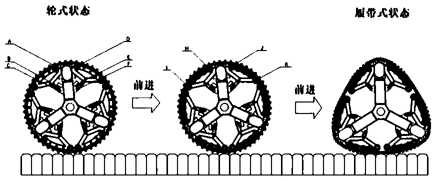
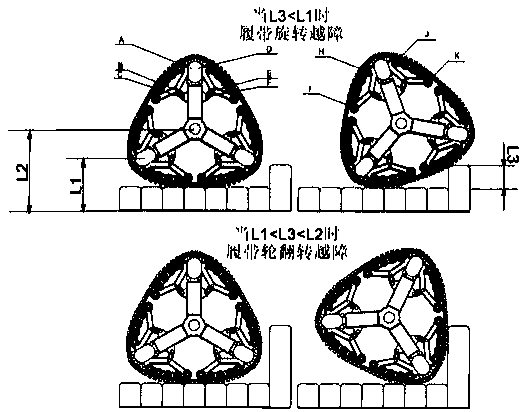
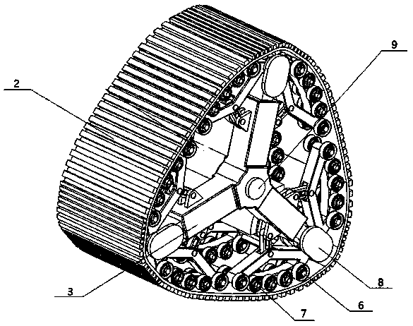
The invention discloses a magnetically driven crawler wheel capable of switching a wheel state and a crawler state. The wheel includes a fixed-length crawler and a driving device driving the fixed-length crawler to rotate. The driving device includes a cage and driving brake assemblies. Each cage includes inner brackets and outer fixing frame devices. The outer fixing frame devices are symmetrically fixed on the left and right sides of the inner brackets. Each outer fixing frame device includes outer brackets and a bracket connecting sleeve. The outer brackets are several. The several outer brackets are evenly distributed on the outer circumference of the corresponding bracket connecting sleeves. An actuator for switching a state of the fixed-length crawler is connected to each outer bracket. Each driving brake assembly includes a magnetic rotor and a driving stator driving the corresponding magnetic rotor to rotate. The driving stators are fixed to the inner brackets. Each magnetic rotor is rotatably connected between the actuators on the left and right sides of the corresponding inner bracket. The magnetic rotors are engaged with the fixed-length crawler to drive the fixed-lengthcrawler to rotate. The magnetically driven crawler wheel capable of switching the wheel state and the crawler state can switch the wheel state and the crawler state according to different road conditions, which improves the practicability.

Description

technical field [0001] The invention relates to the technical field of vehicle walking, in particular to a magnetically driven crawler wheel that can switch between a wheel-type state and a crawler-type state. Background technique [0002] The problems to be solved by all-terrain vehicles are: adaptability to complex environments, good obstacle-surmounting ability and certain speed. At present, common all-terrain vehicle traveling mechanisms are divided into leg type, wheel type, crawler type, compound type and the like. Although the leg-type driving mechanism has good adaptability and strong obstacle-crossing ability, it also has the disadvantages of too complicated structure, low moving efficiency, and difficult control; the composite driving mechanism has multiple sets of drive systems, and the structure and control are relatively complicated. But it is suitable for some special circumstances. Therefore, these two forms are less used. The wheel and the crawler have bec...

Claims


Application Information

Patent Timeline
IPC IPC(8): B62D55/08B62D55/10B62D55/04H02K7/00
Inventor 葛晨阳臧利国金浩王泽正李瑶薇王政正刘晓明
Owner NANJING INST OF TECH
Why Eureka
Try Eureka