
Spinning machine with spindle lifting installation

A spinning frame and spindle technology, which is applied in textiles and papermaking, can solve the problems of slow development of high-speed and large-roll technology, and achieve the effects of convenient and quick maintenance, reduced industrial loss, and extended life

Pending Publication Date: 2019-06-14
江阴华方佳友智能设备有限公司
View PDF0 Cites 0 Cited by
  • Summary
  • Abstract
  • Description
  • Claims
  • Application Information

AI Technical Summary

Problems solved by technology

From the above analysis, it can be seen that the spinning frame needs to achieve high-speed large packages and handle the contradiction between spinning production efficiency and power consumption. The existing technology has not been able to break through the contradiction between high-speed large packages and high energy consumption, which has led to the development of high-speed large package technology. slow

Method used

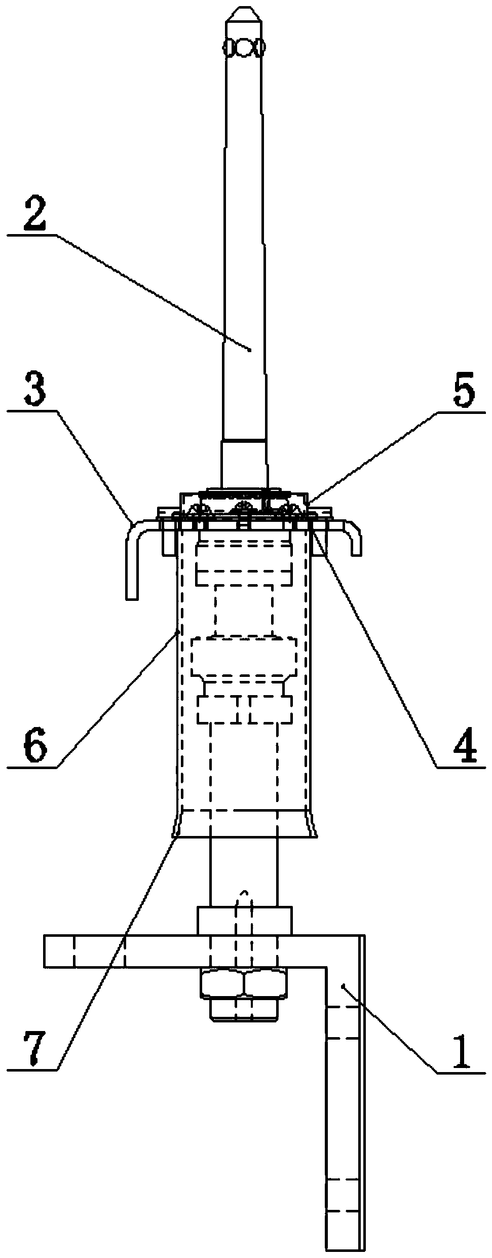
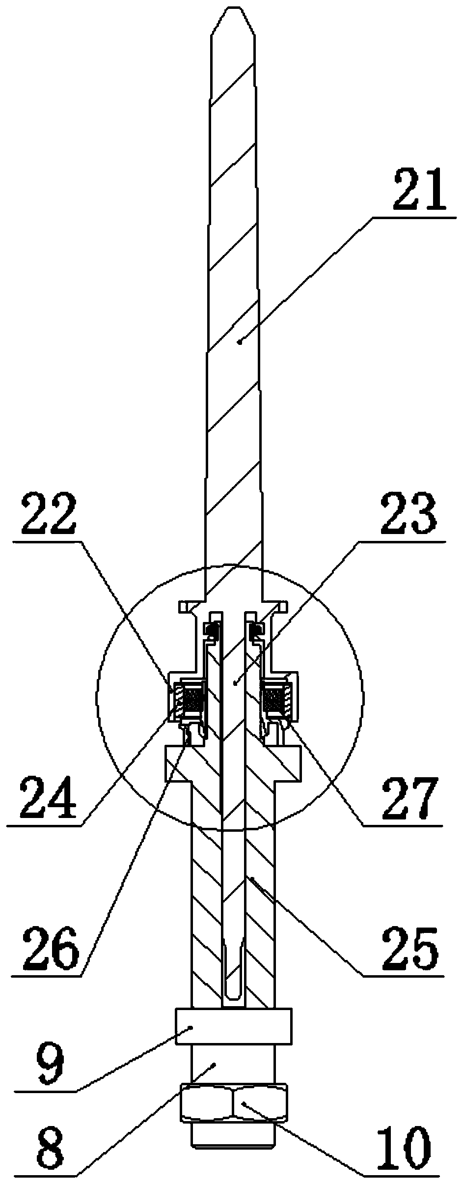
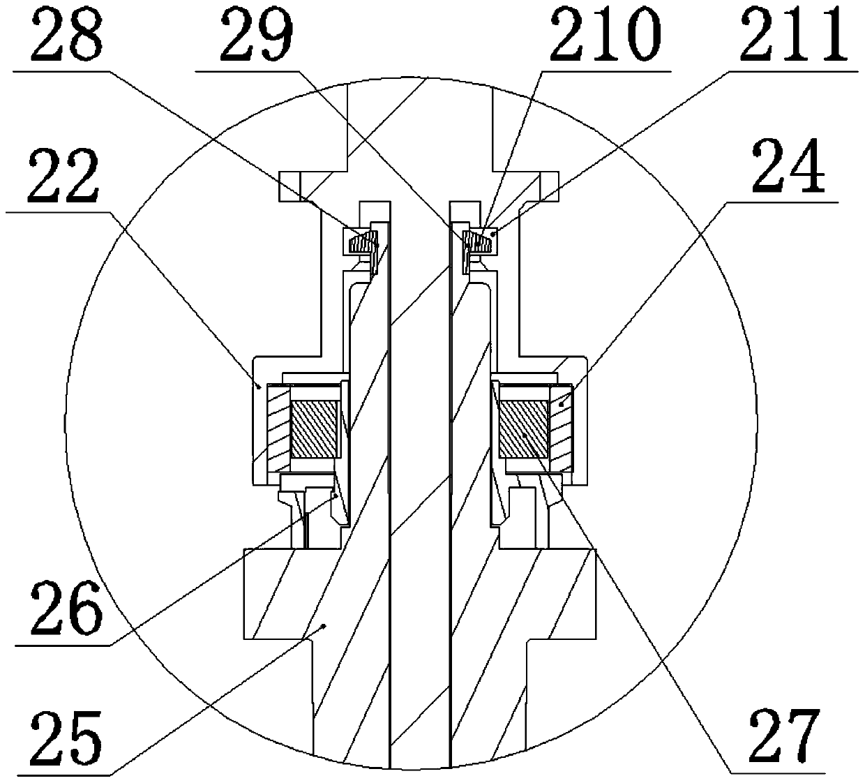

Image

  • Spinning machine with spindle lifting installation
  • Spinning machine with spindle lifting installation
  • Spinning machine with spindle lifting installation

Examples


Embodiment Construction

[0046] The present invention will be further described in detail below in conjunction with the accompanying drawings and embodiments.

[0047] Such as Figure 1 ~ Figure 3 As shown, a spinning frame in which the spindle is raised and installed in this embodiment includes a dragon tendon 1, a row of spindles 2 is arranged on the dragon tendon 1, and a ring plate 3 is arranged above the dragon tendon 1. The ring plate 3 is provided with a row of through holes 4, the spindles 2 correspond to the through holes 4 one by one, the spindles 2 are mounted in the through holes 4, and the upper side of the through holes 4 is provided with a ring ring 5 , the lower side of the through hole 4 is provided with an energy-saving sleeve 6;

[0048] The lower end of the energy-saving sleeve 6 is provided with a trumpet-shaped opening 7;

[0049] The energy-saving sleeve 6 is connected with the ring plate 3 by screws;

[0050] The diameter of the energy-saving sleeve 6 is slightly larger than...


PUM


Abstract

The invention relates to a spinning machine with spindle lifting installation. The machine comprises a dragon rib (1), a row of spindles (2) are arranged on the dragon rib (1), a steel collar plate (3) is arranged above the dragon rib (1), a row of through holes (4) are formed in the steel collar plate (3), the spindles (2) are in one-to-one correspondence with the through holes (4), the spindles(2) are inserted in the through holes (4), the upper sides of the through holes (4) are provided with steel collar rings (5), and the lower sides of the through holes (4) are provided with energy saving sleeves (6). According to the machine, the energy saving sleeves are mounted at the bottom of the steel collar plate, the spindles are raised to provide the space for the energy saving sleeves to move up and down, and the energy saving sleeves can effectively eliminate harmful lateral airflow, reduce the generation of harmful airflow of the spinning, have a beneficial effect on reducing the endof a spinning yarn, can reduce the maximum power consumption of the single spindle by 50%, greatly improve the spindle speed, increase the rolling package, reduce the overall energy consumption of the machine, have a significant energy saving effect, and provide convenience for market promotion.

Description

technical field [0001] The invention relates to a spinning frame with a raised spindle and belongs to the technical field of spinning machinery. Background technique [0002] In the production process of spinning mills, the spinning process accounts for about 70% of the entire spinning process (of which the energy consumption of spinning air conditioning accounts for 30% in the spinning workshop), the development direction of the ring spinning frame is high-speed, large roll packaging can improve production efficiency. However, increasing the spindle speed and increasing the size of the bobbin package will result in a substantial increase in energy consumption. According to measurement and analysis, in the spinning process of spun yarn, the power used for the drafting part is very small (about 5%), and the power consumption of the twisting and winding of the traveler to form the balloon only accounts for 10%. High-speed rotation, the loss of the spindle transmission bearin...

Claims


Application Information

Patent Timeline
Patent Type & Authority Applications(China)
IPC IPC(8): D01H7/08
Inventor 贾殿友陆荣海
Owner 江阴华方佳友智能设备有限公司
Learn More