
A design method of splitter vane for impeller of low specific speed centrifugal pump

A centrifugal pump impeller and splitter vane technology, which is applied to components, pumps, and pump elements of pumping devices for elastic fluids, can solve the problem of single factors, high cost of twisted blades, and insufficient consideration of the internal flow field changes of splitter vanes Influence of other issues, to achieve a good shunt effect, improve the outlet velocity distribution, improve the effect of work performance

Active Publication Date: 2020-11-03
JIANGSU UNIV
View PDF12 Cites 0 Cited by
  • Summary
  • Abstract
  • Description
  • Claims
  • Application Information

AI Technical Summary

Problems solved by technology

In the prior art, the energy gradient function K can be used to determine a reasonable diverter vane inlet offset angle, but this method considers a single factor and is only suitable for preliminary optimization
In the prior art, the equal flow points of each cross-section are also determined through the flow velocity distribution to facilitate the construction of twisted blade profiles, but the cost of twisted blades is high, and the principle of equal flow does not fully consider the influence of splitter blades on internal flow field changes

Method used


Image

  • A design method of splitter vane for impeller of low specific speed centrifugal pump
  • A design method of splitter vane for impeller of low specific speed centrifugal pump
  • A design method of splitter vane for impeller of low specific speed centrifugal pump

Examples


Embodiment Construction

[0033] Embodiments of the present invention are described in detail below, examples of which are shown in the drawings, wherein the same or similar reference numerals designate the same or similar elements or elements having the same or similar functions throughout. The embodiments described below by referring to the figures are exemplary and are intended to explain the present invention and should not be construed as limiting the present invention.

[0034] In describing the present invention, it is to be understood that the terms "central", "longitudinal", "transverse", "length", "width", "thickness", "upper", "lower", "axial", The orientation or positional relationship indicated by "radial", "vertical", "horizontal", "inner", "outer", etc. is based on the orientation or positional relationship shown in the drawings, and is only for the convenience of describing the present invention and simplifying the description , rather than indicating or implying that the device or elem...


PUM


Abstract

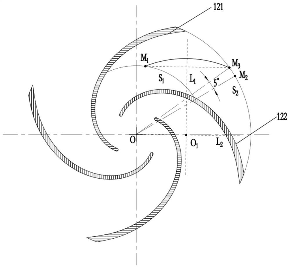
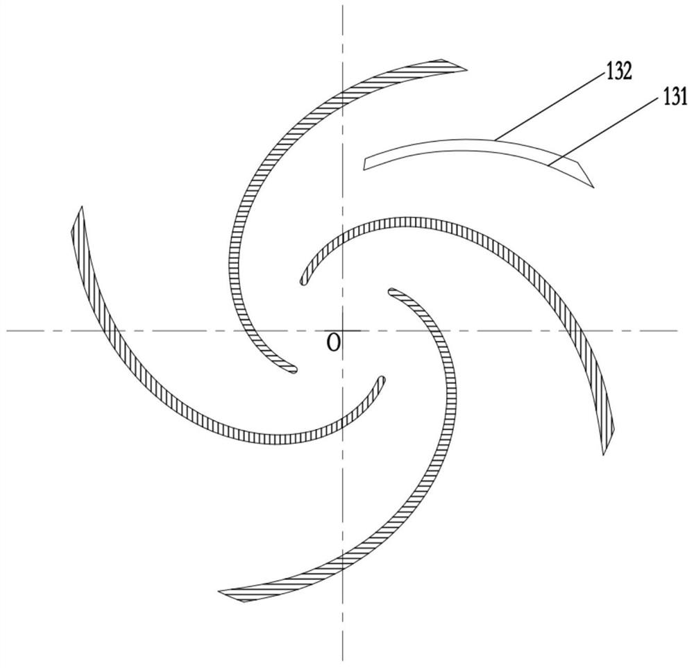
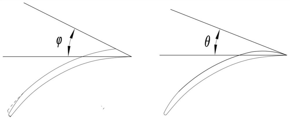
The invention provides a design method of low-specific speed centrifugal pump impeller splitter blades. The design method of the low-specific speed centrifugal pump impeller splitter blades comprisesthe steps that on an impeller plane projection drawing, an inlet and outlet polarization method is adopted to obtain a splitter blade inlet and outlet end point in an arc of a flow channel between adjacent long blades; the circle center is determined according to the impeller center and the splitter blade inlet and outlet end point, and used as an arc to connect the splitter blade inlet and outletend point to obtain a splitter blade pressure surface shaped line; the pressure surface shaped line is thickened through a dotting method to obtain a splitter blade suction surface shaped line, and the two shaped lines are closed to obtain a splitter blade preliminary model; and tip relief is carried out on the splitter blade inlet and outlet pressure surface. According to the design method of the low-specific speed centrifugal pump impeller splitter blades, the internal flow stability of an impeller can be effectively improved, impeller outlet flow field distribution under a non-design working condition is obviously improved, flow losses in the impeller are reduced, meanwhile, pressure pulsation caused by rotor-stator interaction between the impeller and a volute is reduced, and the working performance of a low-specific speed centrifugal pump is improved under the condition of not improving the cost.

Description

technical field [0001] The invention relates to the field of impeller design of centrifugal pumps, in particular to a design method for splitter vanes of impellers of low specific speed centrifugal pumps. Background technique [0002] With the transformation and upgrading of my country's economy, energy conservation research has been paid more and more attention. The pump is one of the key equipment in the "Electric Motor System Energy Conservation Project", and it is the most widely used general-purpose machinery besides the motor. According to statistics, nearly 20% of the world's electric energy consumption is related to pumps, so the research on energy saving of pump products is very necessary. [0003] The vane centrifugal pump is the most widely used type of pump, among which the low specific speed centrifugal pump is widely used in many fields such as agricultural drainage and irrigation, urban water supply, fire protection, petroleum, and chemical industry. The bla...

Claims


Application Information

Patent Timeline
Patent Type & Authority Patents(China)
IPC IPC(8): F04D29/24F04D29/66
Inventor 张金凤蔡海坤袁寿其陈圣波徐捷李亚林
Owner JIANGSU UNIV
Learn More