
Image collecting system of shaft detecting device and image collecting method of image collecting system

An image acquisition system and image acquisition technology, applied in the direction of instruments, optical devices, and optical testing of defects/defects, can solve the problems of accuracy and efficiency not reaching the expected effect, fewer types of measurement tasks, and difficulty in online measurement. Achieve the effect of reducing manual operation, high degree of automation, and complete measurement parameters

Inactive Publication Date: 2019-06-14
WUHAN TEXTILE UNIV
View PDF6 Cites 2 Cited by
  • Summary
  • Abstract
  • Description
  • Claims
  • Application Information

AI Technical Summary

Problems solved by technology

At present, the measurement methods for shaft parts are divided into contact measurement and non-contact measurement. Using contact measurement, the work intensity is high, the efficiency is low, and it is difficult to achieve online measurement. Non-contact measurement overcomes the above-mentioned defects of contact measurement. , but most non-contact measurement tasks have fewer types of measurement tasks, which fail to fully meet the needs of parameter measurement of shaft parts, and at the same time, the accuracy and efficiency of measurement are not up to expectations

Method used


Image

  • Image collecting system of shaft detecting device and image collecting method of image collecting system
  • Image collecting system of shaft detecting device and image collecting method of image collecting system
  • Image collecting system of shaft detecting device and image collecting method of image collecting system

Examples


Embodiment Construction

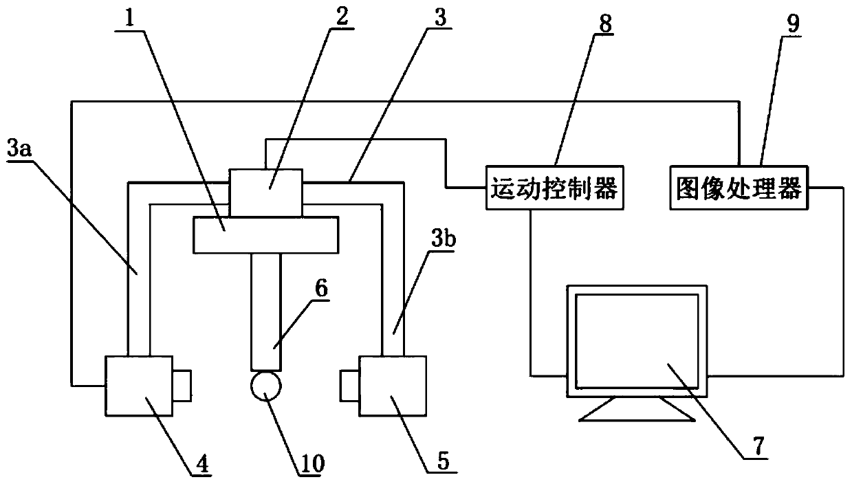
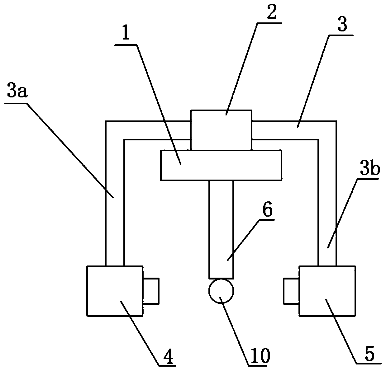
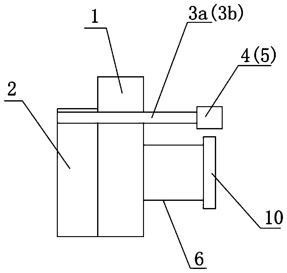
[0027] see as figure 1 and figure 2 As shown, it is a specific embodiment of the image acquisition system of the axis inspection instrument of the present invention, which includes a base 1, a moving translation platform 2 and a workpiece fixing frame 6, the moving translation platform 2 is arranged on the back of the base 1, and the workpiece to be tested The fixed frame 6 is arranged on the front of the base 1, the moving translation platform 2 is connected with the support frame 3, the left end of the support frame 3 is provided with the lens support frame 3a, the right end is provided with the light source support frame 3b, the lens support frame 3a and the light source support frame 3b is symmetrical to the base 1, a camera 4 is fixed on the lens support frame 3a, a light source 5 is fixed on the light source support frame 3b, and the lens of the camera 4 is coaxially opposite to the light source 5;

[0028] Also include PC 7, motion controller 8 and image processor 9, ...


PUM


Abstract

The invention discloses an image collecting system of a shaft detecting device and an image collecting method of the image collecting system. The image collecting system of the shaft detecting devicecomprises a base, a moving translation stage and a to-be-tested fixing tool rack. The moving translation stage is arranged on the back surface of the base, the to-be-tested fixing rack is arranged onthe front surface of the base, the moving translation stage is connected with a supporting rack, a lens supporting rack and a light source supporting rack are arranged at the two ends of the supporting rack, the lens supporting rack and the light source supporting rack are symmetrically arranged, a camera is fixed to the lens supporting rack, a light source is fixed to the light source supportingrack, and a lens of the camera is opposite to the light source in a center parallel mode. The image collecting system of the shaft detecting device further comprises a PC machine, a moving controllerand an image processor, the PC machine is electrically connected with the moving controller and the image processor, the moving controller is electrically connected with the moving translation stage,and the image processor is electrically connected with the camera. According to the image collecting system of the shaft detecting device and the image collecting method of the image collecting system, measurable parameters are complete, the automation degree is high, the shaft-like parts are subjected to parameter measuring by using an image processing technology, the measuring precision is high,and the situation of damaging due to part contacting is avoided.

Description

technical field [0001] The invention relates to the technical field of detection of shaft parts, in particular to an image collection system of a shaft tester and an image collection method thereof. Background technique [0002] The quality of mechanical product parts includes dimensional accuracy, shape and position accuracy, surface roughness, and heat treatment defects, among which the main dimensional accuracy of parts is the most basic content that reflects the quality of mechanical products. Shaft parts are widely used in machinery, automobile, electromechanical and other industries. The machining accuracy of shaft parts directly affects the processing quality of products, so the detection of shaft parts is particularly important. At present, the measurement methods for shaft parts are divided into contact measurement and non-contact measurement. Using contact measurement, the work intensity is high, the efficiency is low, and it is difficult to achieve online measurem...

Claims


Application Information

Patent Timeline
IPC IPC(8): G01B11/00G01N21/88
Inventor 沈满德陈思杰周利兵张法全闵玉瑾
Owner WUHAN TEXTILE UNIV
Learn More