
Rotor blade displacement field measuring method based on blade end timing and system thereof

A rotor blade, displacement field technology, applied in measurement devices, machine/structural component testing, vibration testing, etc., can solve the problems of low survival rate, low reliability and continuous working time, achieve high measurement accuracy, easy to online The effect of simple measurement and calculation process

Active Publication Date: 2019-06-14
XI AN JIAOTONG UNIV
View PDF7 Cites 16 Cited by
  • Summary
  • Abstract
  • Description
  • Claims
  • Application Information

AI Technical Summary

Problems solved by technology

For a long time, aeroengine blades have achieved dynamic strain measurement by pasting strain gauges on the surface of rotor blades, which can only measure dynamic strain at limited positions on limited blades, and their reliability and continuous working time are low, especially in high temperature environments. A large number of strain gauges are arranged on the blade, often only a few strain gauges can obtain effective information, and the survival rate is extremely low

Method used


Image

  • Rotor blade displacement field measuring method based on blade end timing and system thereof
  • Rotor blade displacement field measuring method based on blade end timing and system thereof
  • Rotor blade displacement field measuring method based on blade end timing and system thereof

Examples


Embodiment Construction

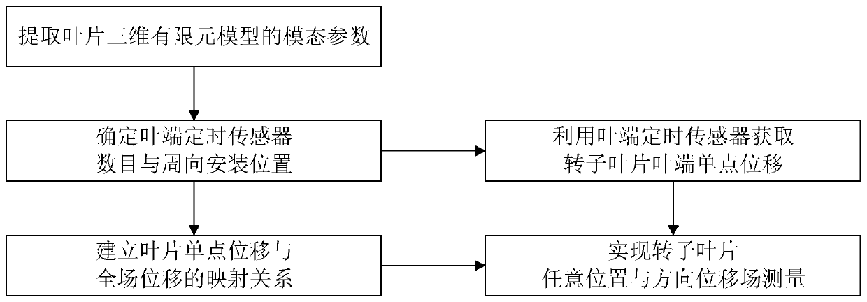
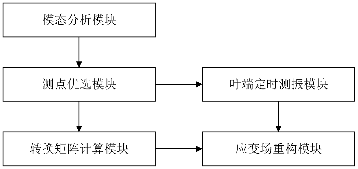
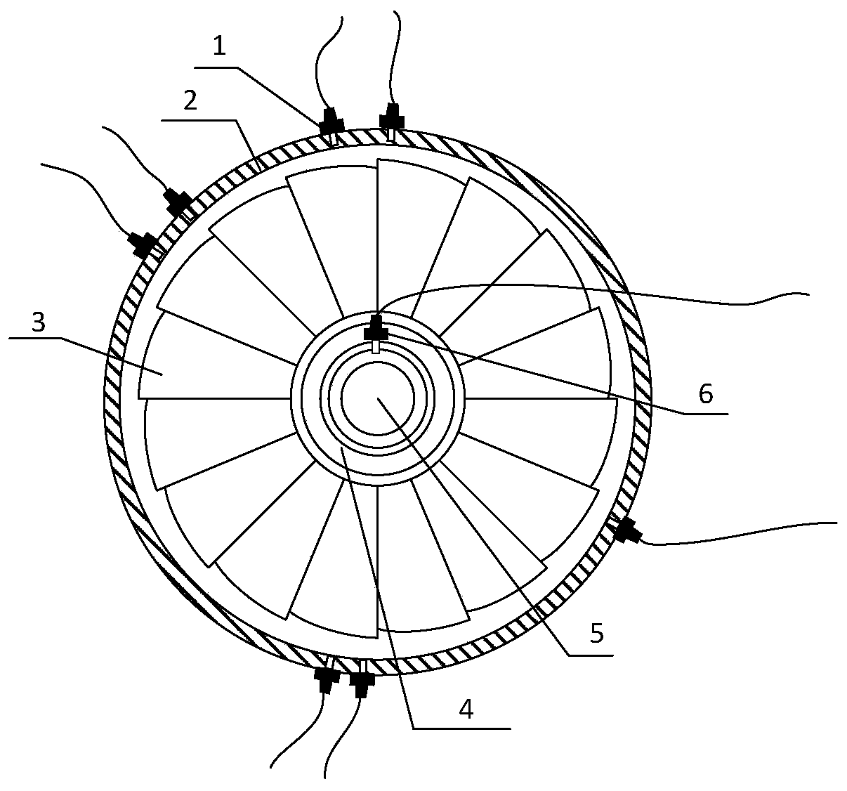
[0052] The following will refer to the attached Figure 1 to Figure 8 Specific examples of the present invention are described in more detail. Although specific embodiments of the invention are shown in the drawings, it should be understood that the invention may be embodied in various forms and is not limited to the embodiments set forth herein. Rather, these embodiments are provided for more thorough understanding of the present invention and to fully convey the scope of the present invention to those skilled in the art.

[0053] It should be noted that certain terms are used in the specification and claims to refer to specific components. Those skilled in the art should understand that they may use different terms to refer to the same component. The specification and claims do not use differences in nouns as a way of distinguishing components, but use differences in functions of components as a criterion for distinguishing. "Includes" or "comprises" mentioned throughout ...


PUM


Abstract

The invention discloses a rotor blade displacement filed measuring method based on a blade end timing and a system thereof. The method comprises the following steps: establishing a three-dimensional finite element model of a rotor blade to be measured, and extracting a modal parameter of the three-dimensional finite element model; determining a blade end timing sensor number and a peripheral mounting position; establishing a mapping relationship between single-point displacement and comprehensive-field displacement of the blade; and acquiring the rotor blade end single-point displacement basedon the blade end timing sensors, wherein the single-point displacement is acquired at any position and in any direction based on the mapping relationship. Through adoption of the method provided by the invention, the reconstruction of the overall rotor blade displacement field of the blade can be realized by using the blade end finite measuring points, so that measurement of all node displacements on the surface and inside of the rotor blade can be realized under the multi-modular vibration. The calculation process is simple, and online measurement can be performed easily.

Description

technical field [0001] The invention belongs to the technical field of non-contact vibration testing of aeroengine rotor blades, in particular to a method and system for measuring rotor blade displacement field based on blade end timing. Background technique [0002] The integrity of the blade directly affects the safe operation of the overall structure of the aeroengine. Affected by factors such as harsh working environment and strong alternating loads, it is very easy to generate vibration fatigue cracks during service and cause serious accidents. High cycle fatigue caused by excessive blade vibration is the main failure mode of aeroengine blades. The high cycle fatigue of the rotor blade is mainly caused by the dynamic stress caused by various aerodynamic loads and mechanical loads, and a large number of cycles can accumulate fatigue cracks in a short period of time, especially when the blade resonates, the dynamic stress can easily lead to the fatigue failure of the blad...

Claims


Application Information

Patent Timeline
IPC IPC(8): G01B21/02G01M7/02
Inventor 乔百杰翟智刘金鑫曹宏瑞陈雪峰
Owner XI AN JIAOTONG UNIV
Learn More