
Electronic component

A technology of electronic components and external electrodes, applied in the direction of electrical components, transformer/inductor parts, circuits, etc., can solve the problems of improving impedance characteristics, coil occupation, etc., and achieve the effect of improving impedance characteristics

Active Publication Date: 2019-06-14
MURATA MFG CO LTD
View PDF8 Cites 2 Cited by
  • Summary
  • Abstract
  • Description
  • Claims
  • Application Information

AI Technical Summary

Problems solved by technology

[0007] However, there is a problem that the space inside the coil is occupied by three via holes, and it is difficult to improve the impedance characteristics by increasing the number of turns of the coil or disposing an iron core inside the coil, etc.

Method used


Image

  • Electronic component
  • Electronic component
  • Electronic component

Examples


Embodiment Construction

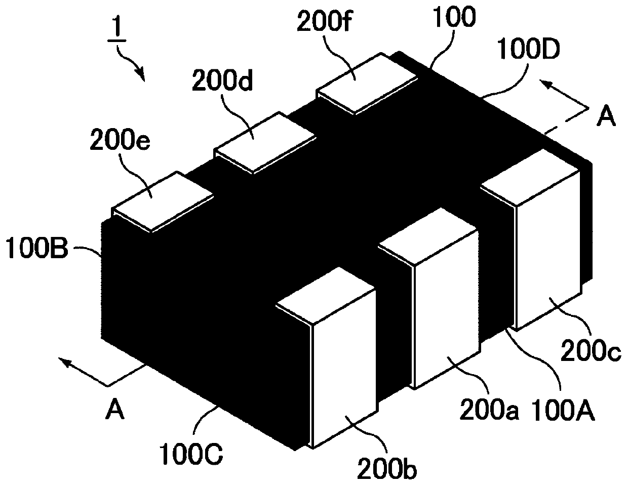
[0035] Hereinafter, the electronic component of the present invention will be described.

[0036] However, the present invention is not limited to the following configurations, and can be appropriately changed and applied within a range that does not change the gist of the present invention. In addition, a combination of two or more of the preferred configurations of the present invention described below also belongs to the present invention.

[0037] [electronic parts]

[0038] First, the electronic component of the present invention will be described.

[0039] The electronic component of the present invention is an electronic component formed by laminating a plurality of coil conductor layers. The coil conductor layer is formed by forming a coil conductor having a coil pattern on the surface of an insulating layer. The above-mentioned electronic component is characterized in that it comprises: The bottom surface side lead-out electrode layer, the primary coil conductor lay...


PUM

PropertyMeasurementUnit
distanceaaaaaaaaaa
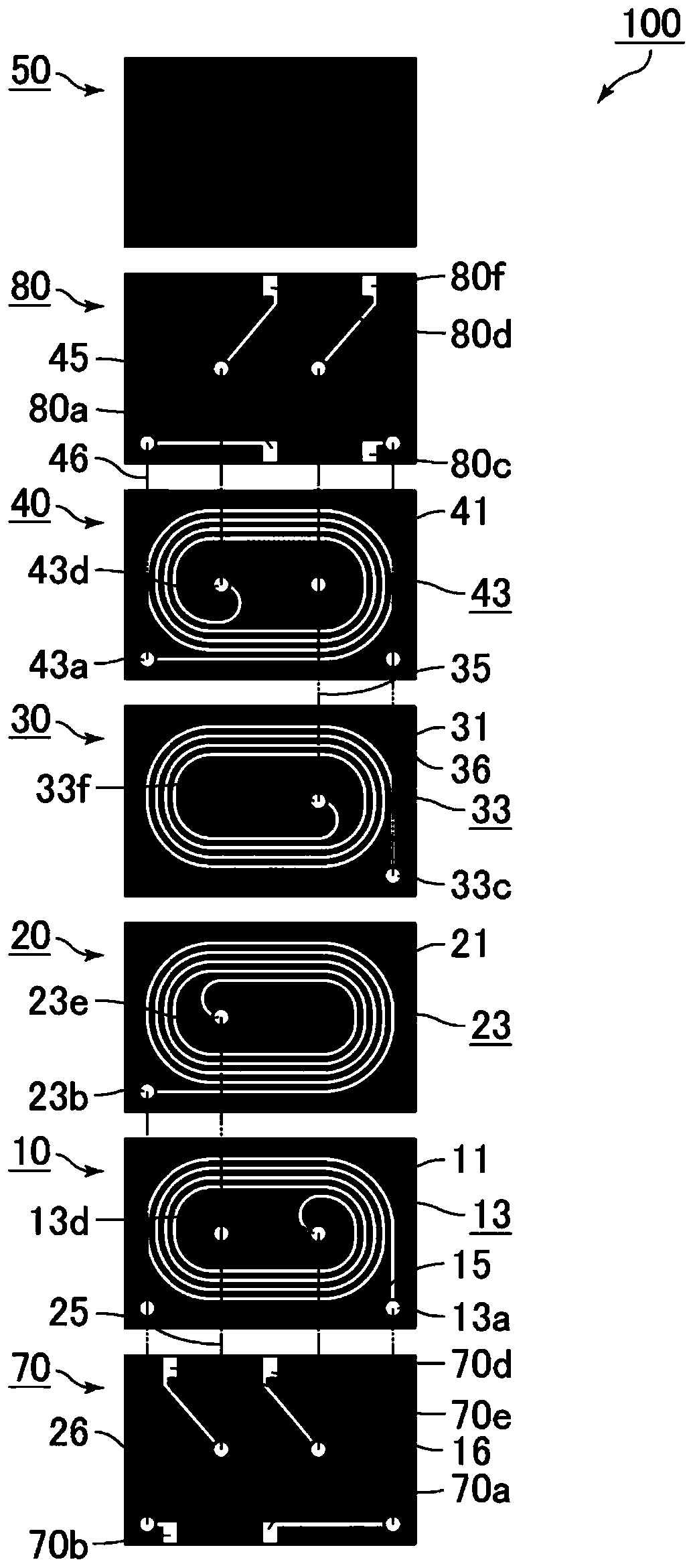
sizeaaaaaaaaaa
lengthaaaaaaaaaa

Abstract

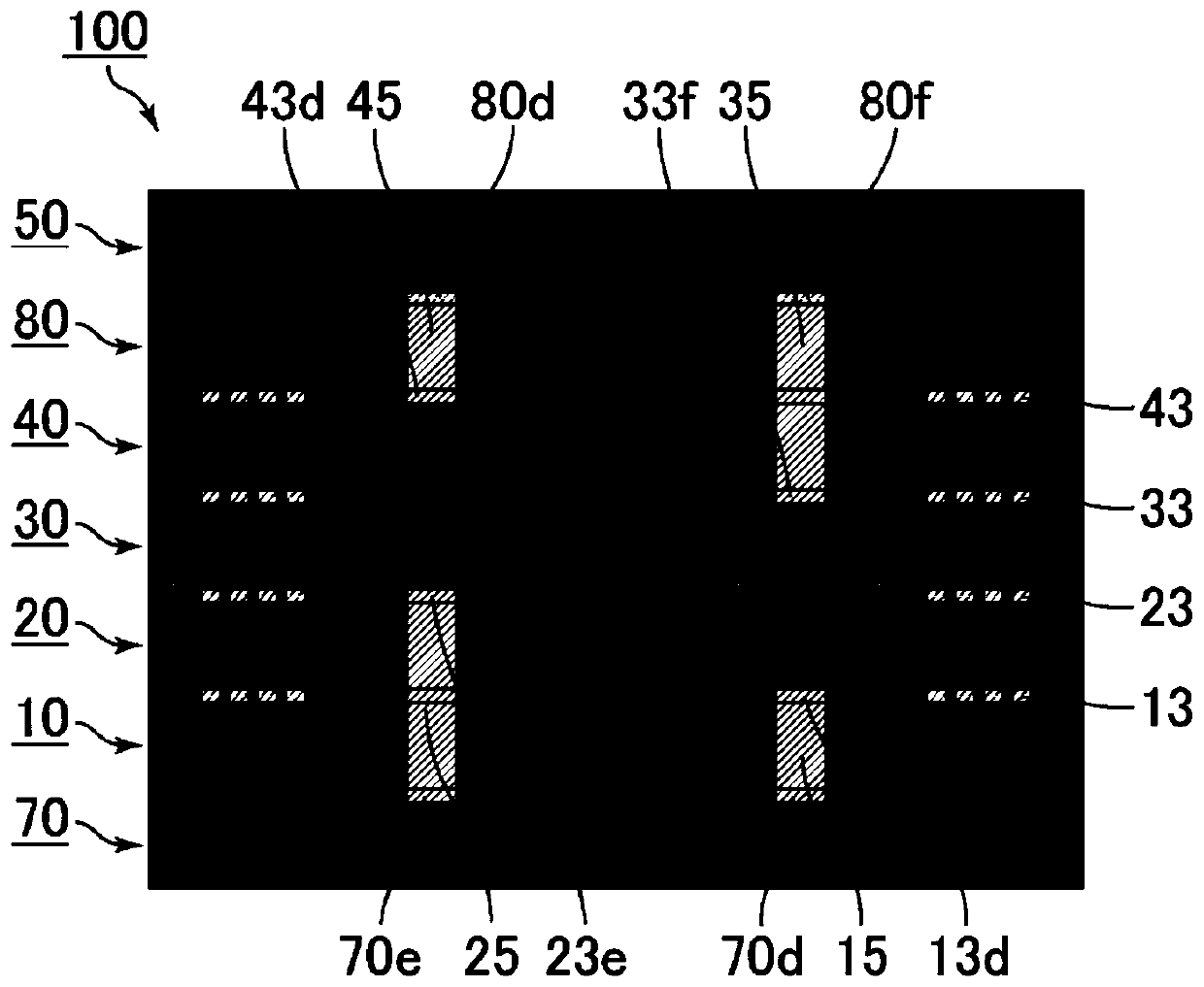
The invention provides an electronic component capable of improving an impedance characteristic. The electronic component includes: a laminated body in which a bottom surface side extraction electrodelayer, a primary coil conductor layer, a secondary coil conductor layer, a tertiary coil conductor layer, a parallel primary coil conductor layer, and an upper surface side extraction electrode layerare laminated in order; and first to sixth external electrodes arranged on the surface of the laminated body, wherein the primary coil conductor is connected to the first and fourth external electrodes; the secondary coil conductor is connected to the second and fifth external electrodes; the tertiary coil conductor is connected to the third and sixth external electrodes; the parallel primary coil conductor is connected to the first and fourth external electrodes; the primary coil conductor is connected in parallel with the parallel primary coil conductor; and the via conductors disposed inside the coil pattern are formed in all of the coil conductor layers constituting the laminated body, and the maximum number of the via conductors inside the coil pattern is two.

Description

technical field [0001] The present invention relates to electronic components. Background technique [0002] In the past, as a digital data transmission standard for connecting the main IC, the display, and the camera in mobile devices, the MIPI (Mobile Industry Processor Interface: Mobile Industry Processor Interface) D-PHY standard was adopted to transmit differential signals using two transmission lines. The way. [0003] When such a differential signal is transmitted, common mode noise is generated, so a filter (common mode filter) for removing the common mode noise is used. [0004] In recent years, with the increase in the number of images of the camera and the increase in the frame rate, a further increase in the data transfer rate is required. As a standard corresponding to such an increase in the data transmission speed, there is the MIPI-C-PHY standard in which three transmission lines are used to improve the data transmission speed. When there are three transmi...

Claims


Application Information

Patent Timeline
Patent Type & Authority Applications(China)
IPC IPC(8): H01F17/00H01F27/28H01F27/29H01F27/32
CPCH01F17/0033H01F41/046H01F2017/0066H01F17/0013H01F27/292H01F2017/0093H01F41/0233H01F27/2804
Inventor 松浦耕平滨野守裕都筑庆一
Owner MURATA MFG CO LTD
Learn More