Electric wire stripping combined device of cable insulating layer

A technology of cable insulation and combination device, applied in the direction of dismantling/armoring cable equipment, etc., can solve the problems of easily damaged cable inner core, bulky, complex structure, etc., achieve simple structure, high stripping speed, and prevent the stripping shaft from being separated. Effect

Active Publication Date: 2019-06-14
STATE GRID ZHEJIANG JIASHAN POWER SUPPLY CO LTD +1
View PDF14 Cites 6 Cited by
  • Summary
  • Abstract
  • Description
  • Claims
  • Application Information

AI Technical Summary

Problems solved by technology

The above-mentioned device can electrically strip the cables, but the device itself has a complex structure and a large volume, which is not conducive to carrying, and the inner core of the cable is easily damaged during the gas cutting process.

Method used


Image

  • Electric wire stripping combined device of cable insulating layer
  • Electric wire stripping combined device of cable insulating layer
  • Electric wire stripping combined device of cable insulating layer

Examples


Embodiment 1

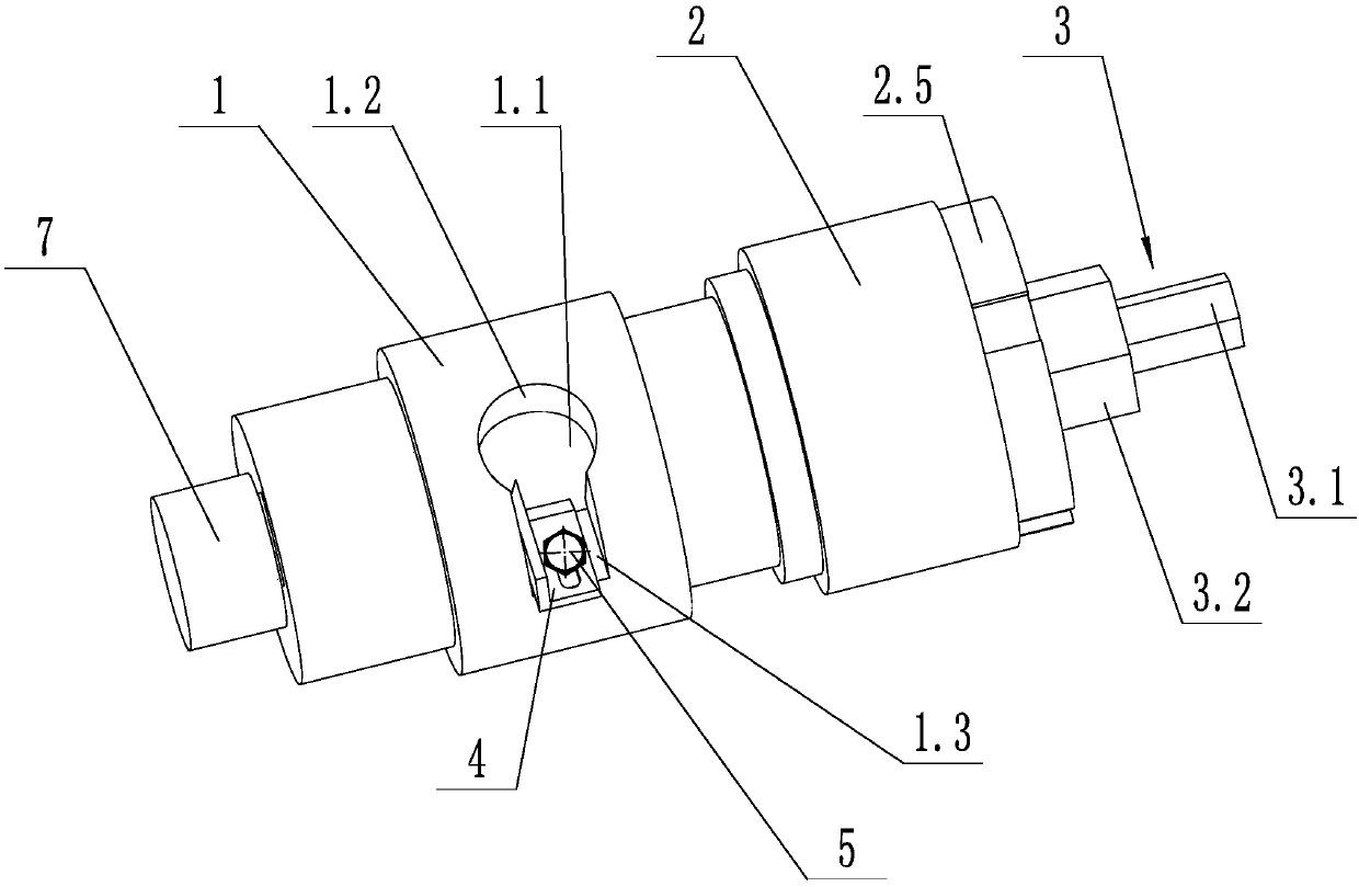
[0025] As shown in the figure, an electric cable insulation layer stripping combination device includes a stripping shaft 1 and a connecting shaft 3, the connecting shaft 3 includes a coaxially connected connecting section 3.1 and an adjusting section 3.2, and the adjusting section 3.2 is coaxial with the stripping shaft 1 Fixed, the connecting section 3.1 is adapted to the gun head of the pistol drill; the center of the stripping shaft 1 is provided with a stripping inner cavity 1.1 for placing the cable 7, and the side wall of the stripping shaft 1 is provided with a chip removal hole 1.2 and a knife groove hole 1.3, the chip removal hole 1.2 is connected with the slit hole 1.3 and connected with the stripping inner chamber 1.1, the slit hole 1.3 is provided with a cutter 4, the blade of the cutter 4 is fixed to the stripping shaft 1, and the cutter 4 The cutting edge faces toward the side of chip removal hole 1.2. The outer insulating layer of the cable can be quickly strip...

Embodiment 2

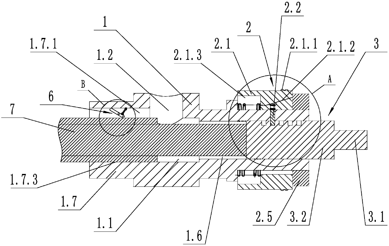
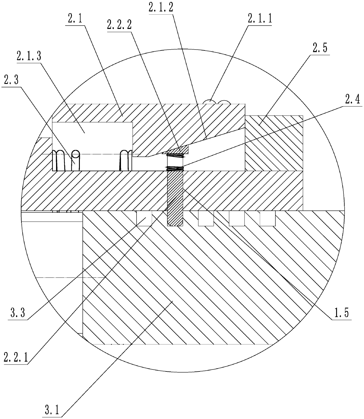
[0029] As shown in the figure, on the basis of Embodiment 1, the side wall of the adjustment section 3.2 is provided with several locking grooves 3.3 distributed along the axis of the connection section 3.1, and the stripping shaft 1 is provided with a slide hole 1.5, an adjustment device 2 and the locking inner cavity 1.6 that communicates with the stripping inner cavity 1.1 and is coaxial; the adjustment section 3.2 is arranged in the locking inner cavity 1.6 and is adapted to the locking inner cavity 1.6, and the adjustment device 2 includes an adjustment sleeve 2.1 , locking piece 2.2, first spring 2.3, second spring 2.4 and locking ring 2.5; the adjustment sleeve 2.1 is coaxially sleeved on the stripping shaft 1, and the inner wall of the adjustment sleeve 2.1 is provided with an adjustment chute 2.1 .2 and the spring ring groove 2.1.3, the first spring 2.3 is coaxially sleeved on the stripping shaft 1 and located in the spring ring groove 2.1.3, one end of the first sprin...

Embodiment 3

[0033] As shown in the figure, on the basis of Embodiment 1 or Embodiment 2, the end of the stripping shaft 1 away from the connecting shaft 3 is provided with a guide sleeve 1.7, and a guide sleeve 1.7 is provided on the guide sleeve 1.7 to communicate with the stripping inner cavity 1.1. Guide cavity 1.7.3, guide sleeve 1.7 and stripping shaft 1 are coaxially fixed, the inner wall of the guide sleeve 1.7 is provided with a mounting groove 1.7.1, and the side wall of the mounting groove 1.7.1 is provided with a rotating hole. A locking device 6 is provided in the groove 1.7.1, and the locking device 6 includes a tension spring 6.1, a locking lever 6.2 and a locking wheel 6.3, and the locking lever 6.2 includes a first locking section 6.2.1, a rotating The shaft 6.2.2 and the second locking section 6.2.3, the quality of the first locking section 6.2.1 is greater than the mass of the second locking section 6.2.3, and the center of gravity of the first locking section 6.2.1 is 6....


PUM


Abstract

The invention discloses an electric wire stripping combined device of a cable insulating layer. The electric wire stripping combined device comprises a wire stripping shaft and a connecting shaft, wherein the connecting shaft comprises a connecting section and an adjusting section which are coaxially connected; the adjusting section is coaxially fixed with the wire stripping shaft, and the connecting section is matched with the gun head of a pistol drill; a wire stripping inner cavity used for containing a cable wire is arranged in the wire stripping shaft in the axial direction; a chip removal hole and a cutter groove hole are formed in the side wall of the wire stripping shaft, and the chip removal hole and the cutter groove hole are communicated with each other and are communicated withthe wire stripping inner cavity; and the cutter groove hole is internally provided with a cutter capable of stripping and cutting the outer insulating layer of the cable wire. The electric wire stripping combined device of the cable insulating layer has the advantages that the structure is simple, the carrying is convenient, the cutting efficiency is high, the cable inner core is not easily damaged, and the like.

Description

technical field [0001] The invention relates to the field of electric equipment, in particular to an electric cable insulation layer stripping combined device. Background technique [0002] When the cable is installed, it is necessary to strip the outer insulation of the cable end. In the prior art, manual stripping is generally used. Because the outer insulation layer of the cable is thicker, especially in cold winter, the outer insulation layer of the cable is thicker. Thick manual cuts are difficult and often cut the inner core of the cable. Therefore, it is urgent to invent an electric cable insulation layer stripping combination device, which can quickly strip the outer insulation layer of the cable, and the stripping speed is fast, the effect is good, and the inner core of the cable will not be scratched. At the same time, the device itself is easy to carry . [0003] Chinese Patent Application Publication No. CN106159822B, published on October 31, 2017, titled "A Po...

Claims


Application Information

Patent Timeline
Patent Type & Authority Applications(China)
IPC IPC(8): H02G1/12
Inventor 张冲标马铭佶史建勋郁云忠李飞伟曹吉领曲凯朱迪王帅李俊郁玮刚黄先勇
Owner STATE GRID ZHEJIANG JIASHAN POWER SUPPLY CO LTD
Why Eureka
Try Eureka