Liquid-electricity-gas hybrid power rotor device

A hybrid, liquid-gas technology, applied in electromechanical devices, electrical components, etc., can solve the problems of poor heat dissipation, affecting the stable operation of slip rings, inconvenient equipment winding, etc., to enhance sealing performance and torque, and realize the integration of liquid and electricity Transmission, ensure long-term stable work effect

Active Publication Date: 2019-06-14
SUZHOU SABO IND DESIGN
View PDF11 Cites 0 Cited by
  • Summary
  • Abstract
  • Description
  • Claims
  • Application Information

AI Technical Summary

Problems solved by technology

[0002] With the improvement of precision requirements for modern parts manufacturing and testing, gas static pressure support technology with clean and high precision features has been widely used. Performance and torsion performance are unstable, prone to leakage, and when a large current is supplied, the heat dissipation effect is poor, which seriously affects the stability of the slip ring
In order to solve the problem of rotating and transferring the rotor between dynamic and static, the electric drive part and the liquid-pneumatic drive part are integrated together. However, this design has problems such as inconvenient winding of equipment, and at the same time, the rotor cannot simultaneously realize the transmission of liquid, gas and electricity.

Method used


Image

  • Liquid-electricity-gas hybrid power rotor device
  • Liquid-electricity-gas hybrid power rotor device
  • Liquid-electricity-gas hybrid power rotor device

Examples


Embodiment Construction

[0029] In order to make the technical means, creative features, goals and effects achieved by the present invention easy to understand, the present invention will be further described below in conjunction with specific illustrations.

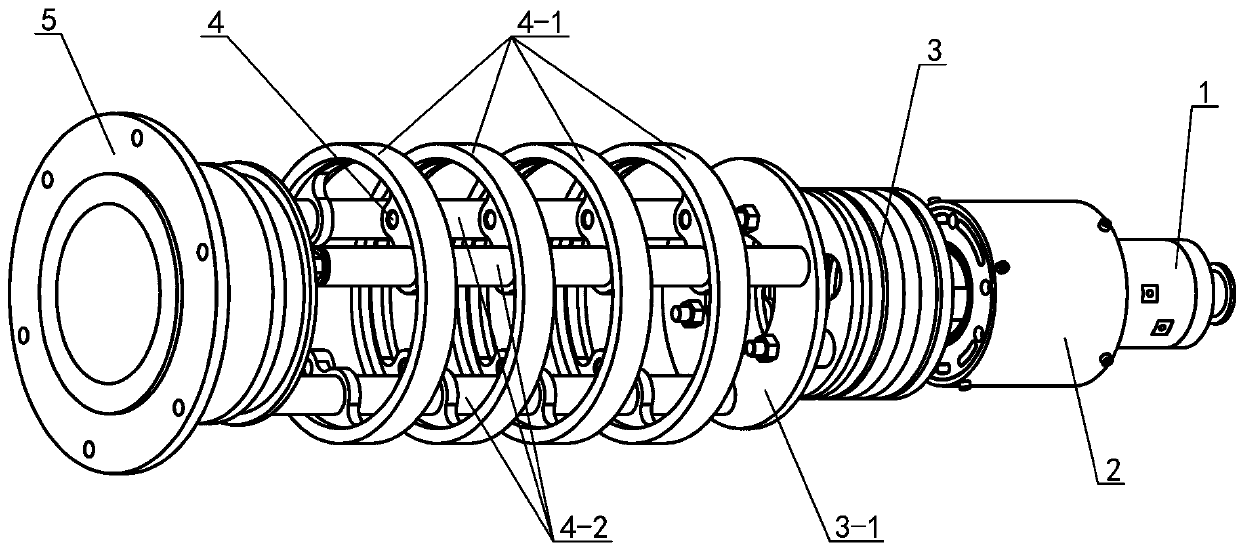
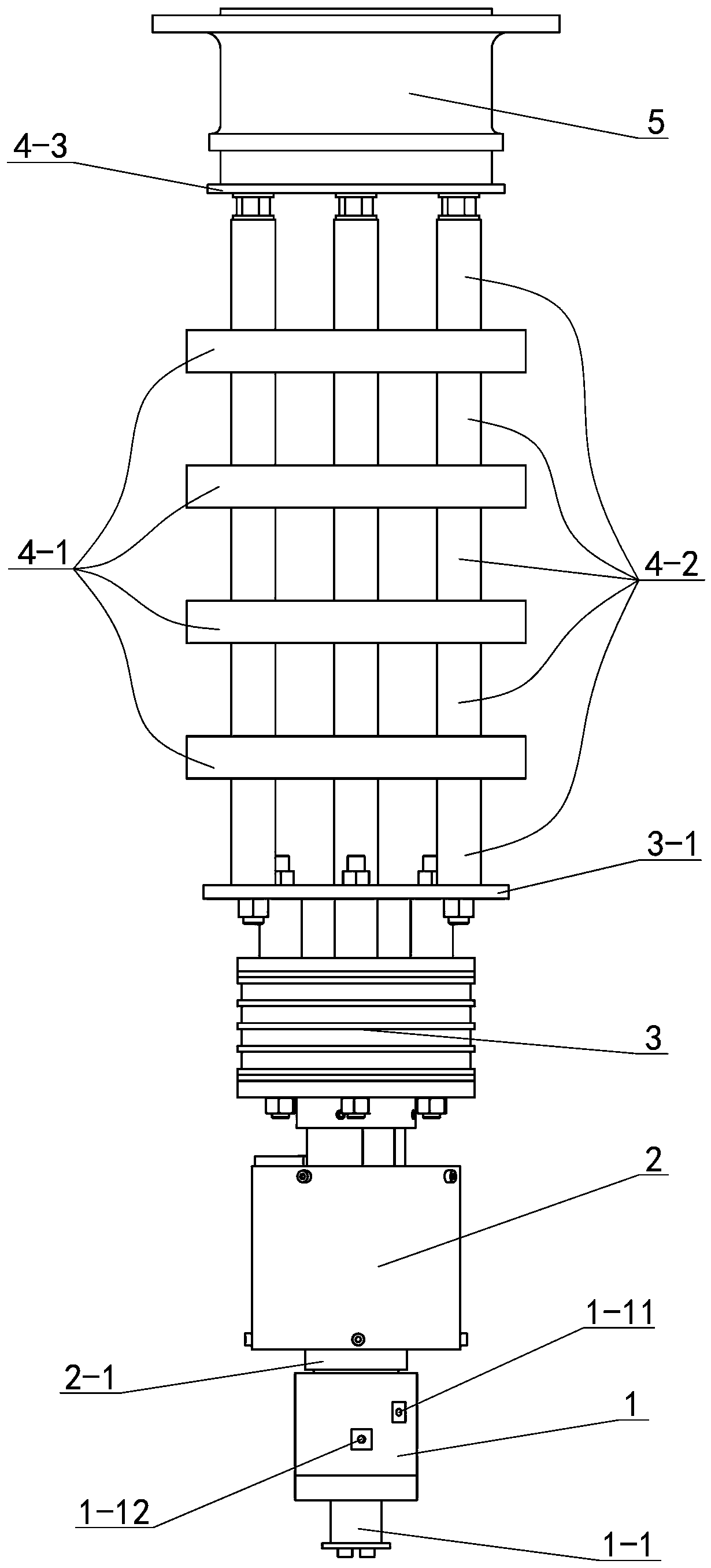
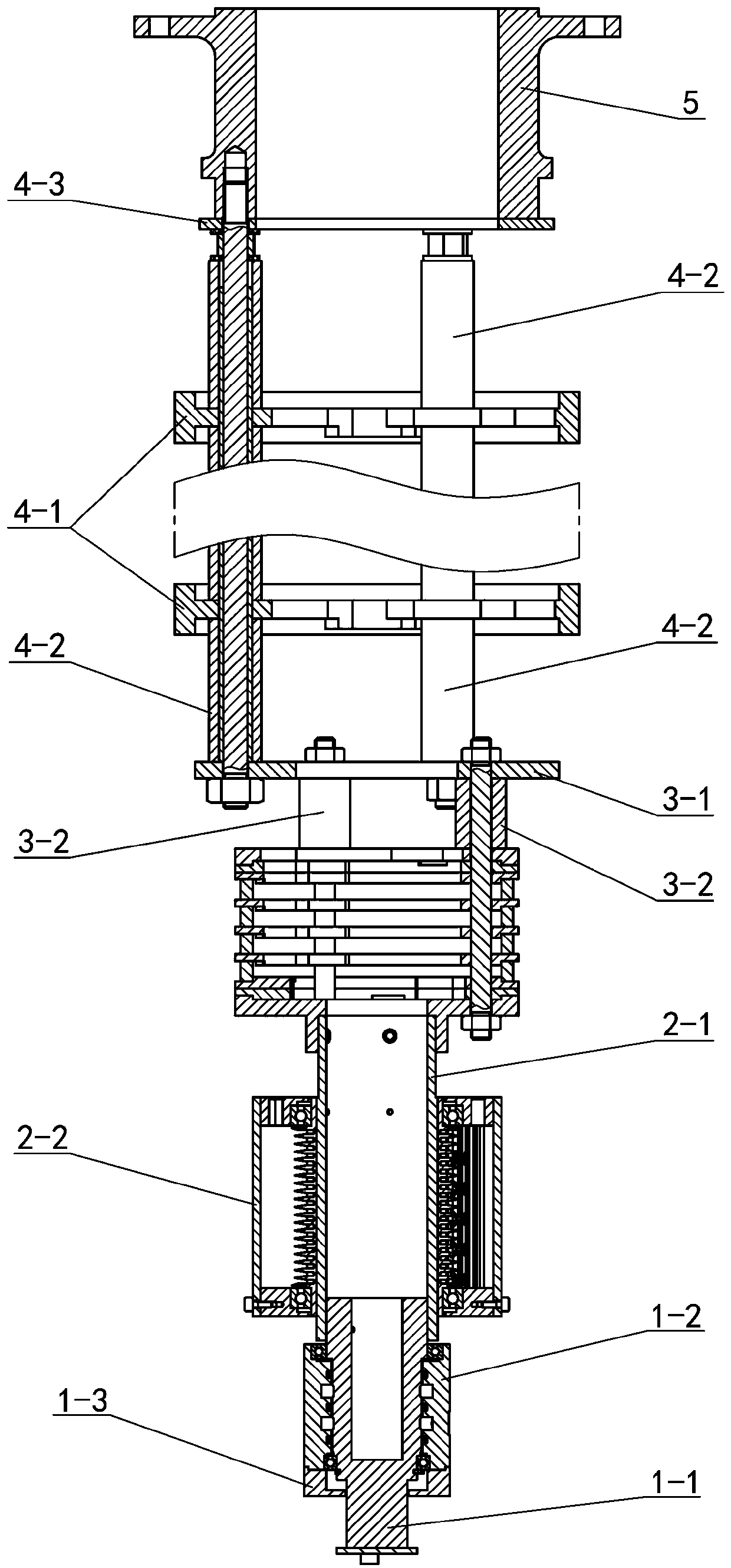
[0030] see Figure 1 to Figure 8 A liquid-electric hybrid rotor device, including a liquid-gas control part 1, a slip ring signal part 2, a conductive power part 3, a conductive high-current part 4 and a rotor flange 5, wherein the rotor flange 5 and the conductive high-current part 4 connection, the conductive large current part 4 is set on the conductive power part 3, the liquid gas control part 1 is tightly connected with the upper end of the slip ring signal part 2, and the lower end of the slip ring signal part 2 is tightly connected with the conductive power part 3. The details of each part The structure is as follows:

[0031]The liquid-gas control part 1 includes a liquid-gas control shaft 1-1, a liquid-gas control housing 1-2, a liquid...


PUM


Abstract

The invention relates to a liquid-electricity-gas hybrid power rotor device. A plurality of large-current conductive copper rings are arranged in a conductive large-current part, the large-current conductive copper rings are contacted with a large-current support pipe to transmit when large-current power is provided, and the cooling structure of the conductive large-current part is effectively optimized; a large-current insulation pipe sleeves a large-current screw rod, and an electric brush is facilitated to be contacted with surfaces of the large-current conductive copper rings all the way so as to further achieve a rotation connection function when a part is relatively rotated; a through hole is formed in a sliding ring core shaft and is used for a rotor line to pass through, and the problem of winding in the device is effectively solved; and shells are respectively arranged on a liquid-gas control part and a sliding ring signal part, so that the sealing performance and the torque of the device are improved, gas is prevented from being leaked, and liquid-electricity-gas integrated transmission is further achieved.

Description

technical field [0001] The invention relates to the technical field of automation equipment, in particular to a hydraulic-electric hybrid rotor device. Background technique [0002] With the improvement of precision requirements for modern parts manufacturing and testing, gas static pressure support technology with clean and high precision features has been widely used. The performance and torque performance are unstable, and leakage is easy to occur. When a large current is supplied, the heat dissipation effect is poor, which seriously affects the stability of the slip ring. In order to solve the problem of rotating and transferring the rotor between dynamic and static, the electric drive part and the liquid-pneumatic drive part are integrated together. However, this design has problems such as inconvenient winding of equipment, and at the same time, the rotor cannot simultaneously realize the transmission of liquid, gas and electricity. . Contents of the invention [0...

Claims


Application Information

Patent Timeline
Patent Type & Authority Applications(China)
IPC IPC(8): H02K13/02
Inventor 徐新明童成彪陈文凯
Owner SUZHOU SABO IND DESIGN
Why Eureka
Try Eureka