
End effector of unbaling robot

A technology of end effector and driving mechanism, applied in the field of intelligent manufacturing, can solve problems such as low degree of automation, and achieve the effect of improving efficiency, ensuring quality and ensuring hygiene

Active Publication Date: 2019-06-18
TAIYUAN UNIVERSITY OF SCIENCE AND TECHNOLOGY
View PDF6 Cites 5 Cited by
  • Summary
  • Abstract
  • Description
  • Claims
  • Application Information

AI Technical Summary

Problems solved by technology

[0005] Therefore, in order to improve the mechanization and low degree of automation of the unbundling process of tubes and bars in the prior art, and to improve the industrial production environment, a kind of unbundling robot end effector is needed

Method used


Image

  • End effector of unbaling robot
  • End effector of unbaling robot
  • End effector of unbaling robot

Examples


Embodiment Construction

[0035] The objects and functions of the present invention and methods for achieving the objects and functions will be clarified by referring to the exemplary embodiments. However, the present invention is not limited to the exemplary embodiments disclosed below; it can be implemented in various forms. The essence of the description is only to help those skilled in the relevant art comprehensively understand the specific details of the present invention. Hereinafter, embodiments of the present invention will be described with reference to the accompanying drawings. In the drawings, the same reference numerals represent the same or similar components, or the same or similar steps.

[0036] In order to solve the problems of low degree of mechanization and automation and low work efficiency in the process of unbundling pipes and rods in the prior art, the present invention provides a binding robot end effector, which uses binocular vision and displacement sensors to bind wires ( ...


PUM


Abstract

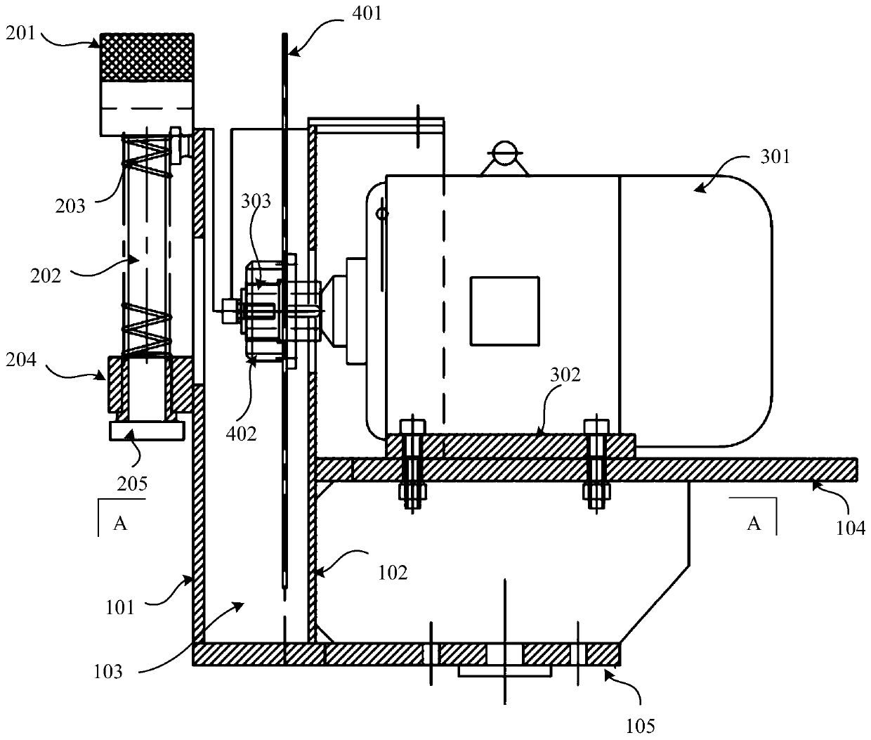
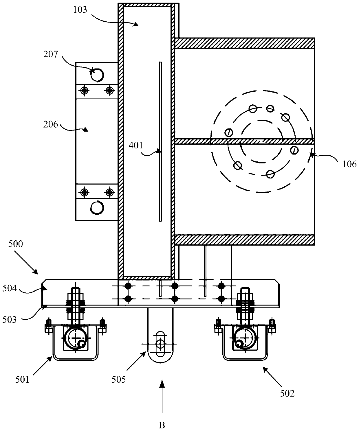
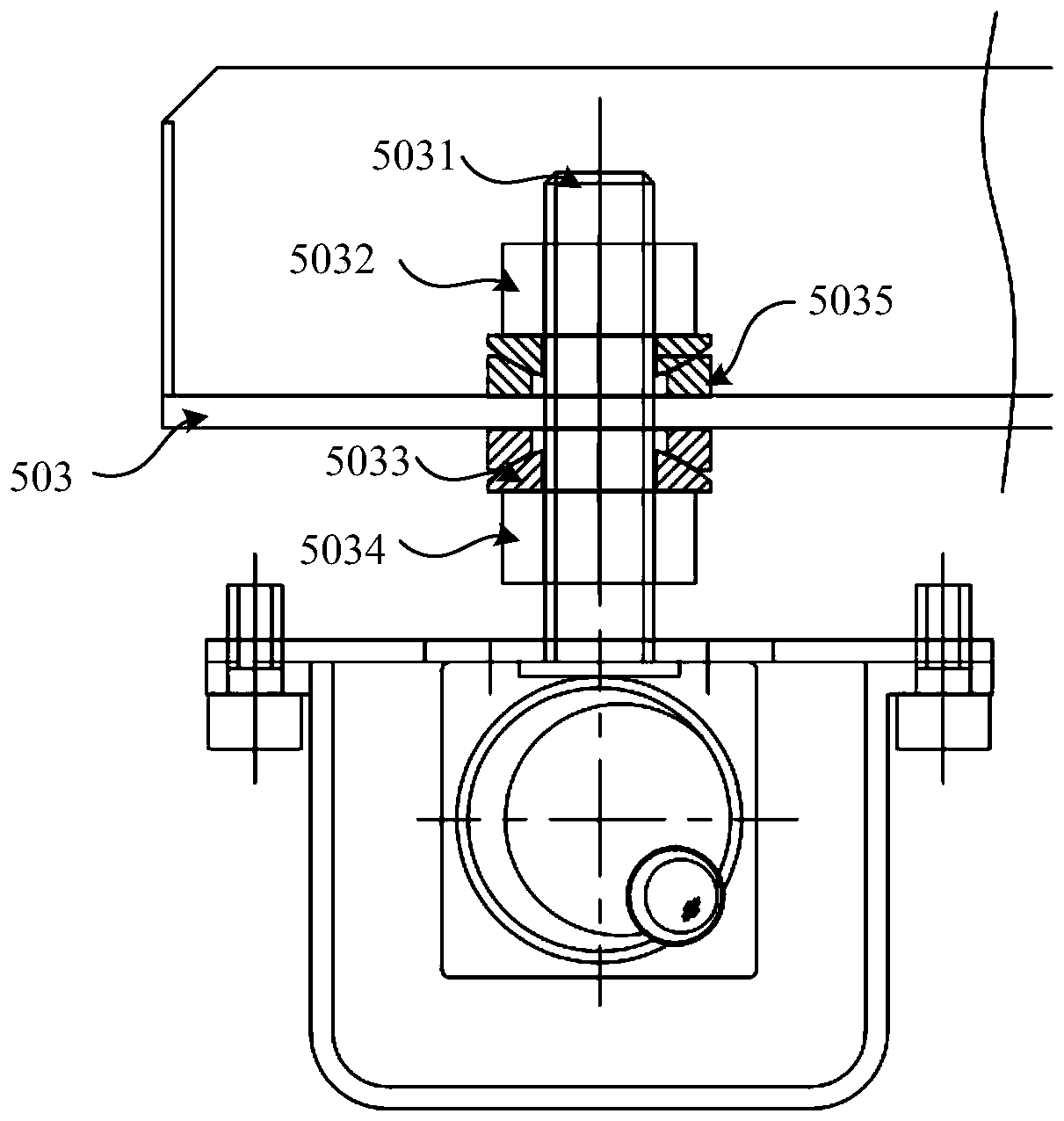
The invention provides an end effector of an unbaling robot. The end effector comprises a bracket, wherein the front end of the bracket is equipped with a magnetic attraction mechanism; the rear end of the bracket is equipped with a drive mechanism; a shearing mechanism is mounted in a space between the magnetic attraction mechanism and the drive mechanism; the drive mechanism drives the shearingmechanism to shear a bundling wire; one side of the bracket is equipped with a detecting mechanism; the detecting mechanism comprises a mounting frame; a first image identification device and a secondimage device, which are symmetrical in position, are arranged on the mounting frame; and a displacement detecting sensor is arranged between the first image identification device and the second imagedevice. The end effector is simple in structure, is high in practicability, is high in intelligent degree; and each unit can cooperatively act to effectively accomplish unbaling operation of rods, sothat the rods are prevented from being scratched.

Description

technical field [0001] The invention relates to the technical field of intelligent manufacturing, in particular to an end effector of an unbundling robot. Background technique [0002] In recent years, more and more attention has been paid to the development of industrial robot technology at home and abroad. According to statistics, my country is the fastest-growing and largest demand market, and the sales growth rate of robots has continued to expand in my country for three consecutive years. Compatible with sales growth, the output of robots in my country has also maintained a high-speed growth. With the change of my country's population structure, the working population has dropped to 72% year by year, and the wage cost of laborers has risen sharply. Many enterprises feel the labor shortage and the decline in profit margins. Using robots to reduce production costs has become an inevitable choice for enterprises to enhance their competitiveness. [0003] After more than ...

Claims


Application Information

Patent Timeline
Patent Type & Authority Applications(China)
IPC IPC(8): B65B69/00
Inventor 马立东仝浩源孟进礼
Owner TAIYUAN UNIVERSITY OF SCIENCE AND TECHNOLOGY
Learn More