
A pothole protection mechanism for an aerial work vehicle

A technology for aerial work vehicles and protection mechanisms, applied in vehicle maintenance, lifting vehicle accessories, safety devices for lifting equipment, etc., can solve problems such as deformation of the protection plate, easy cracking of the protection plate, and difficulty in timely detection of the protection plate, achieving Avoid the effect of demolition

Active Publication Date: 2020-06-30
杭州杭叉高空设备有限公司
View PDF4 Cites 0 Cited by
  • Summary
  • Abstract
  • Description
  • Claims
  • Application Information

AI Technical Summary

Problems solved by technology

[0005] Aiming at the deficiencies in the prior art, the purpose of the present invention is to provide a pothole protection mechanism for aerial work vehicles to solve the problem that when the aerial work vehicles in the prior art are affected by potholes, the support protection plate on the equipment contacts the ground and stretches apart. When the protective plate touches the ground, it is easy to cause the upper end to lose force and exert pressure on the plate to deform the protective plate. The deformed plate is unevenly stressed and affects the balance protection of the aerial work vehicle. Wear and tear, it is difficult to detect in time when using the protection plate, making the protection plate’s bearing force reach the upper limit and it is easy to break

Method used


Image

  • A pothole protection mechanism for an aerial work vehicle
  • A pothole protection mechanism for an aerial work vehicle
  • A pothole protection mechanism for an aerial work vehicle

Examples


Embodiment Construction

[0028] In order to make the technical means, creative features, goals and effects achieved by the present invention easy to understand, the present invention will be further described below in conjunction with specific embodiments.

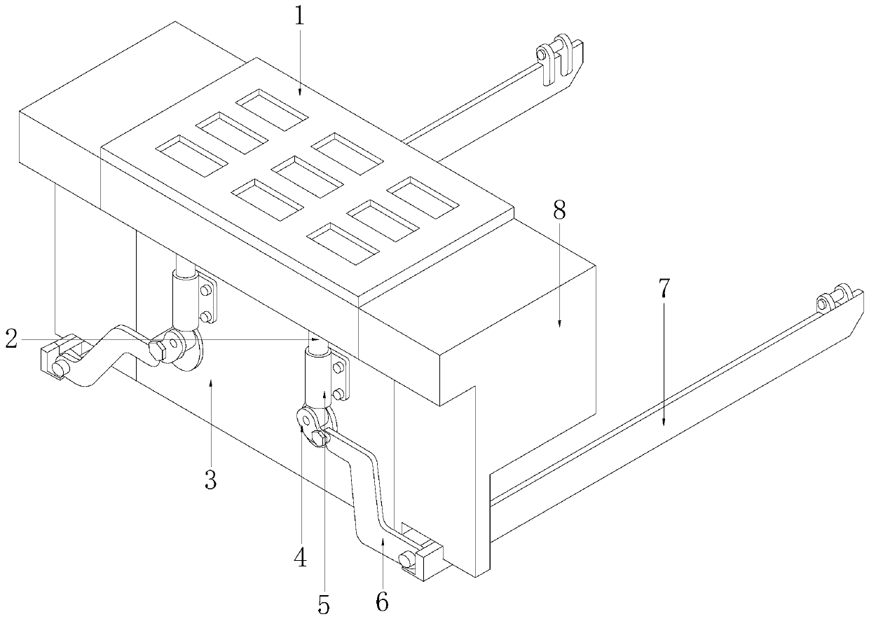
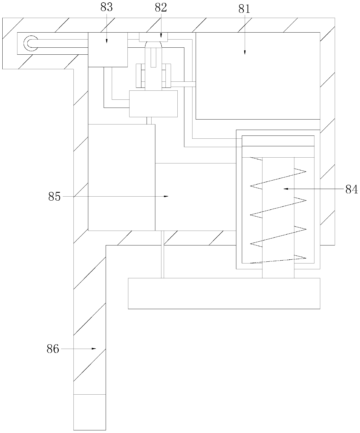
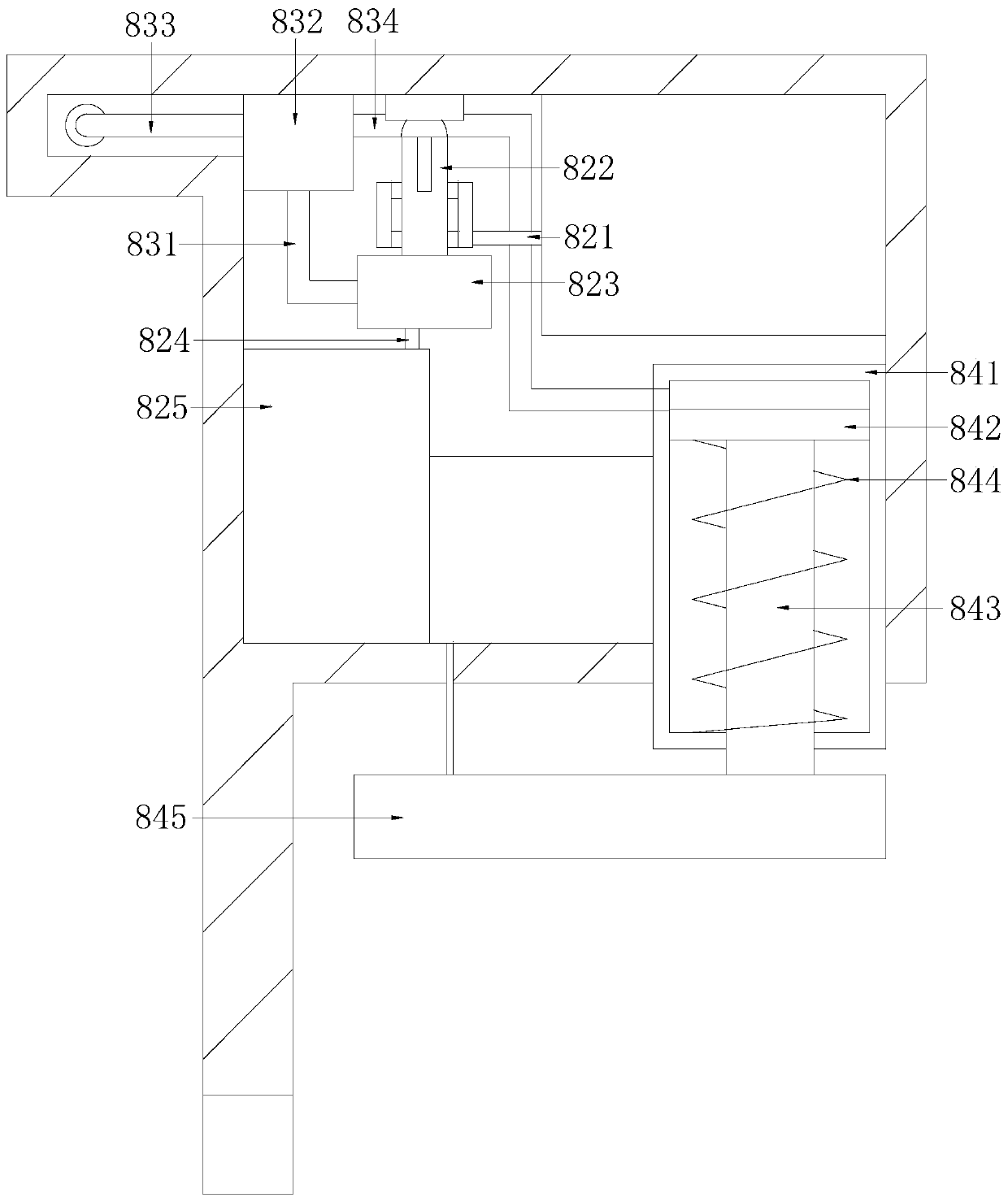
[0029] like Figure 1-Figure 7 As shown, the present invention provides a technical solution for the pothole protection mechanism of aerial work vehicle:

[0030] A pothole protection mechanism for an aerial work vehicle, the structure of which includes a vehicle bottom lead plate 1, a pressing shaft 2, a protection mechanism body 3, a traction swing mechanism 4, a limit fixing ring 5, an interlocking movable plate 6, and a pothole support The protection plate 7, the balanced pressure application stability detection device 8, the lower surface of the vehicle bottom lead plate 1 is connected with the upper surface of the protection mechanism body 3 by electric welding, and the pressing shaft 2 is installed in the protection mechanism in an embedded...


PUM


Abstract

The invention discloses a hole protecting mechanism of an aerial work vehicle. The hole protecting mechanism structurally comprises a car bottom guiding plate, a pressing shaft, a protection mechanismbody, a traction swing mechanism, a limit fixing ring buckle, a linkage movable plate, a pit support protection plate and a balance pressure stabilization detection device, the lower surface of the car bottom guiding plate is connected with the upper surface of the protection mechanism body through an electric welding mode, the pressing shaft is installed on the left surface of the protection mechanism body in an embedded mode, the pressing shaft penetrates through the upper end and the lower end of the limiting fixing ring buckle and is connected with the same axis through an attaching mode,the right surface of the limiting fixing ring buckle is connected with the left surface of the protection mechanism body in an electric welding mode. According to the hole protecting mechanism, whensupporting is carried out, the protection plate is subjected to force application balance by applying the connection pressure through the hydraulic pressure, so that the deformation of the plate surface is prevented from being unbalanced, the ultrasonic waves are arranged in the pressure applying plate to carry out detection imaging on the protection plate in a sound wave manner, so that the situation that the detection needs to be disassembled is avoided, and the maintenance and replacement can be timely known.

Description

technical field [0001] The invention relates to the technical field of high-altitude operation, more precisely, it relates to a pothole protection mechanism for an aerial work vehicle. Background technique [0002] Aerial work is an operation in which people carry out construction at a high place that is vertical to the ground as a reference. Aerial work is generally performed on high-voltage wires, high-rise buildings, etc., and the work platform truck is used to transport workers upwards for construction. vehicle. However, the current pothole protection device has the following disadvantages: [0003] 1. When the aerial work vehicle is affected by potholes, the supporting protective plate on the equipment is in contact with the ground and stretched, and when the protective plate touches the ground, it is easy to cause the upper end to lose force and press the plate to deform the protective plate, and the deformed plate is stressed. Unevenness affects the balance protecti...

Claims


Application Information

Patent Timeline
Patent Type & Authority Patents(China)
IPC IPC(8): B66F11/04B66F17/00B60S9/02
Inventor 陈金芽
Owner 杭州杭叉高空设备有限公司
Learn More