
Meter

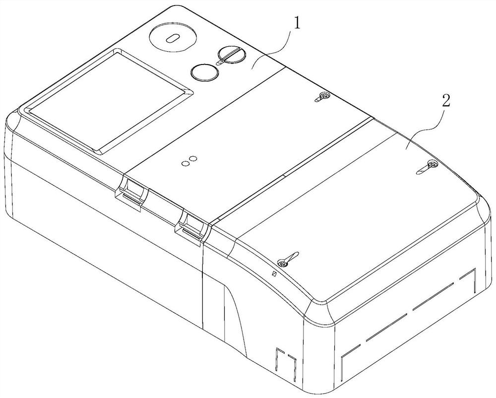
A technology of electric energy meter and conductive sheet is applied in the field of electric energy meter, which can solve the problems of long assembly time and easy heating at the connection, and achieve the effect of small contact thermal resistance, large contact area, and shortened assembly time.

Active Publication Date: 2021-02-05
深圳龙电华鑫控股集团股份有限公司
View PDF15 Cites 0 Cited by
  • Summary
  • Abstract
  • Description
  • Claims
  • Application Information

AI Technical Summary

Problems solved by technology

[0003] The purpose of the present invention is to provide an electric energy meter to solve the technical problems existing in the prior art that the use of screws to fix the relay and the terminal button results in long assembly hours and easy heating at the connection

Method used


Image

  • Meter
  • Meter
  • Meter

Examples


specific Embodiment approach

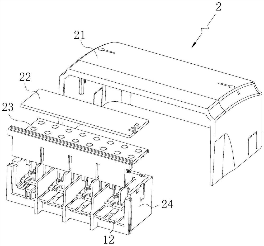
[0046] see Figure 8 As a specific embodiment of the electric energy meter provided by the present invention, the end button assembly 2 also includes an end button upper cover 23 connected to the end button base 24 buckle 2311, the end button upper cover 23 includes a vertical plate 230, and is connected with the end button base 24. The vertical plate 232 is vertically connected to the horizontal plate 231 , the vertical plate 232 is provided with buckles 2311 , and the button base 24 is provided with a slot 2401 which is engaged with the buckles 2311 . The vertical board 230 and the horizontal board 231 can shield the fixing unit. Optionally, the horizontal plate 231 and the bottom wall 241 are parallel to each other, and the vertical plate 232 is parallel to the second side. There may be multiple buckles 2311 on the vertical board 232 , which may be arranged in sequence along the length direction of the vertical board 232 . The slot 2401 on the end button base 24 can be di...


PUM


Abstract

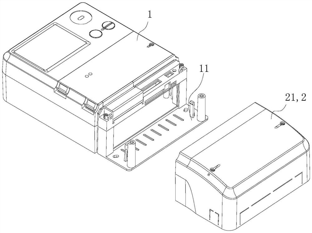
The invention provides an electric energy meter, which includes a casing, a relay and a terminal button assembly. The relay is arranged in the casing, and the conductive sheet of the relay is inserted into the terminal button assembly. Fixed connection, the terminal button base includes a side wall, a bottom wall connected to the side wall, and a limiting plate parallel to the side wall. The side wall, the bottom wall and the limiting plate form a receiving groove for the insertion of the conductive piece. A U-shaped groove is provided to form the main body of the bottom wall and the cantilever beam. The cantilever beam is provided with a first positioning part, and the conductive sheet is provided with a second positioning part matched with the first positioning part. In the electric energy meter provided by the present invention, the side wall, the bottom wall and the limit plate form a receiving groove for inserting the conductive sheet of the relay, and the receiving groove has a certain positioning effect on the conductive sheet, the first positioning part and the second positioning part Cooperate with each other, so that the conductive sheet is completely fixed in the terminal button assembly, without using screws to fix.

Description

technical field [0001] The invention belongs to the technical field of electrical accessories, and more specifically relates to an electric energy meter. Background technique [0002] Energy meters are widely used in large-scale circuit systems. The core device inside the energy meter is a relay. The relay and the terminal button are usually fixed to each other by fasteners such as screws. Specifically: the copper sheet of the screw and the relay and the terminal button The shell is tightly fitted, so that the copper sheet is fixedly connected with the end button. However, when the copper sheet is fixed with screws, the man-hours required to assemble the screws are longer, and the screws increase the contact resistance, causing heat at the connection. Contents of the invention [0003] The object of the present invention is to provide an electric energy meter to solve the technical problems existing in the prior art that the relay and the terminal button are fixed by scre...

Claims


Application Information

Patent Timeline
Patent Type & Authority Patents(China)
IPC IPC(8): G01R11/04
Inventor 祝洋芳
Owner 深圳龙电华鑫控股集团股份有限公司
Learn More