
A test system

A test system and test equipment technology, applied in diode test, electronic circuit test, electronic protection circuit test, etc., can solve problems such as easy failure, unnecessary, defective equipment to be tested, etc.

Inactive Publication Date: 2019-06-18
PHOENIX CONTACT GMBH & CO KG
View PDF5 Cites 0 Cited by
  • Summary
  • Abstract
  • Description
  • Claims
  • Application Information

AI Technical Summary

Problems solved by technology

[0009] However, this means that other UUTs that already meet the initial specification but exhibit less degradation are automatically considered defective or prone to failure, even if they have been identified for which historical data is available
[0010] Therefore, in the past, it often resulted in the replacement of equipment assumed to be faulty or at risk of failure when it was not necessary in the first place

Method used


Image

  • A test system
  • A test system
  • A test system

Examples


Embodiment approach

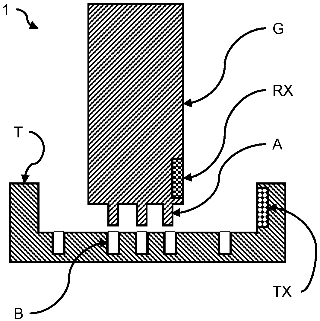
[0061] According to another embodiment of the invention, the memory units C, RX additionally contain data relating to the specification of the device under test.

[0062] This means that, in addition to device-specific measurements, specification-related measurements can also be carried out spontaneously, ie without interrogating internal or external databases, which makes use, for example, in the field significantly easier.

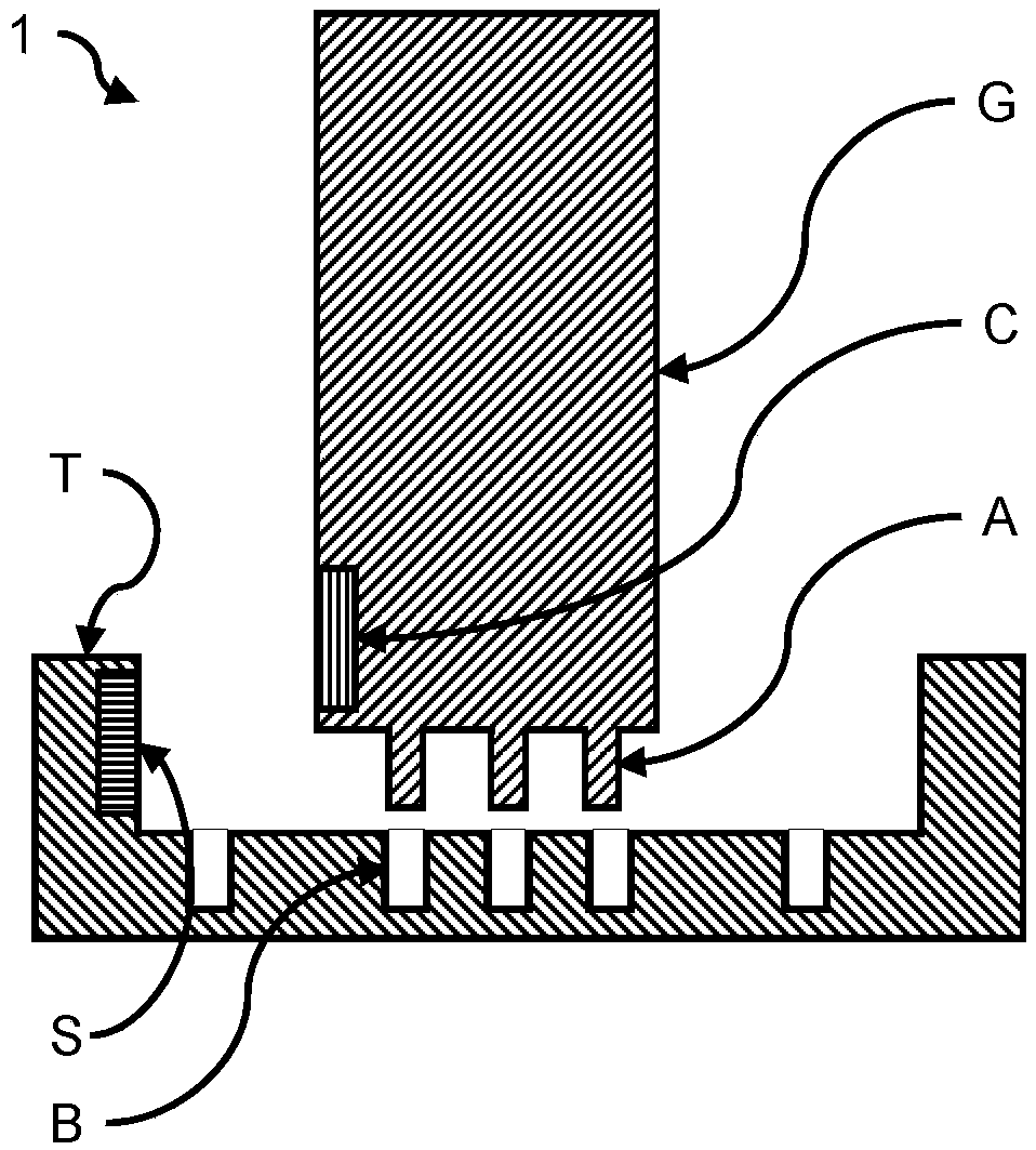
[0063] In another aspect such as figure 2 In the illustrated embodiment, the memory cell C is a multi-dimensional optical code. The reading device S is correspondingly an optical scanner. This is advantageous in environments where high levels of electromagnetic interference exist. Such a code is reliably resistant to damage by electromagnetic interference if the code is applied or provided, for example, by means of a label, laser treatment, printing, electronic paper display or the like.

[0064] In an advantageous configuration, the multidimensional...


PUM


Abstract

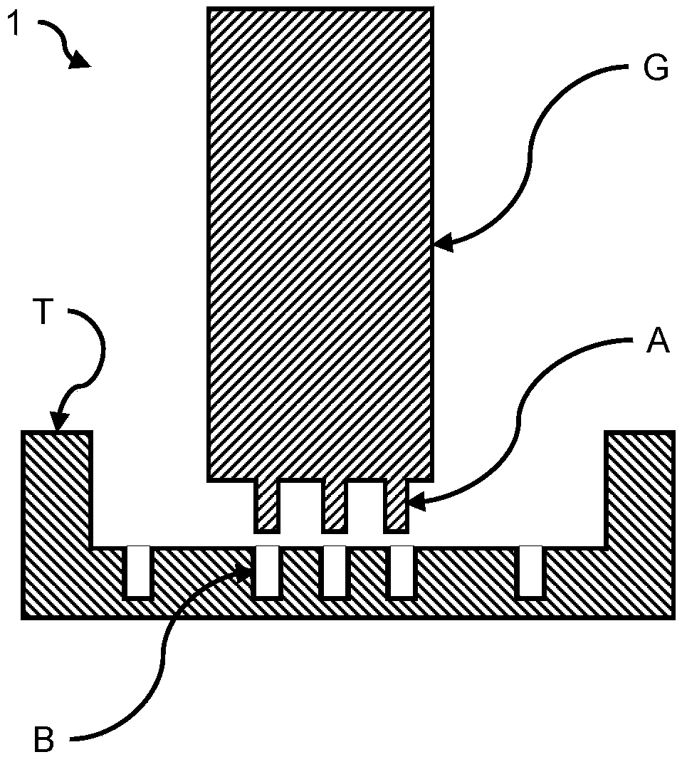
The invention relates to a test system (1) that comprises a to-be-tested device (G) and a test device (T). The to-be-tested device (G) is an electrical device, and has a memory unit (C, RX); the memory unit comprises measurement data of the to-be-tested device (G), wherein the measurement data forms a first data set; the test device (T) has a reading device (S, TX), so that the measurement data ofthe to-be-tested device (G) can be read in a non-contact manner. The test device (T) has a connection socket (B) used for connecting the test device with the to-be-tested device (G) so as to executethe test. The test device (T) identifies to be measured data of the to-be-tested device (G) during measurement, and the measured data constitutes a second data set; the test device (T) evaluates whether the to-be-tested device (G) is still available or faulty based on the first data set and the second data set.

Description

technical field [0001] The invention relates to a testing system. Background technique [0002] Test systems for overvoltage protection devices are known from the prior art. [0003] Overvoltage protection devices need / must be electrically checked for their performance under predetermined circumstances or based on problems within the device. [0004] Current test systems are pre-configured for specific devices, based on a database corresponding to the device type, prior to actual testing. [0005] In the past, therefore, new test equipment had to be purchased separately not only for each manufacturer, but also for each new generation of a manufacturer's product, and / or updated to a new level. [0006] This process is costly. On the one hand, it is necessary to have test equipment from different manufacturers, and on the other hand, to keep said test equipment at the current state of the art. It has also been shown in the past that updates are not always bug-free, and par...

Claims


Application Information

Patent Timeline
IPC IPC(8): G01R31/00G01R1/04
CPCG01R31/2827G01R31/3025G01R31/2637G01R31/2633
Inventor 弗里德里希-埃克哈德·布兰德
Owner PHOENIX CONTACT GMBH & CO KG
Learn More