
A laser direct light and its forward scattered light light trap device

A technology of forward scattered light and direct light, applied in the direction of scattering characteristic measurement, optics, optical components, etc., to achieve the effects of improved safety and storage, overall weight reduction, and large opening diameter

Active Publication Date: 2021-12-14
HEFEI INSTITUTES OF PHYSICAL SCIENCE - CHINESE ACAD OF SCI
View PDF7 Cites 0 Cited by
  • Summary
  • Abstract
  • Description
  • Claims
  • Application Information

AI Technical Summary

Problems solved by technology

At present, there is no suitable optical trap device or solution that can meet the needs of such a large opening and strong extinction ability.

Method used


Image

  • A laser direct light and its forward scattered light light trap device
  • A laser direct light and its forward scattered light light trap device

Examples


Embodiment Construction

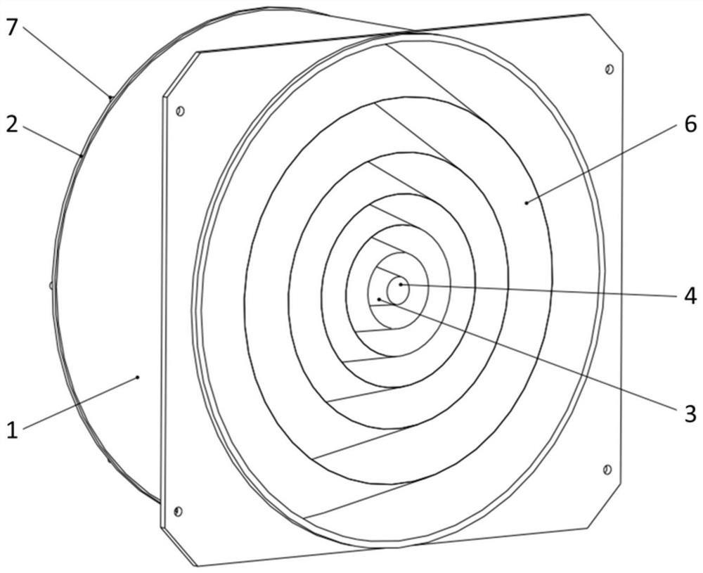
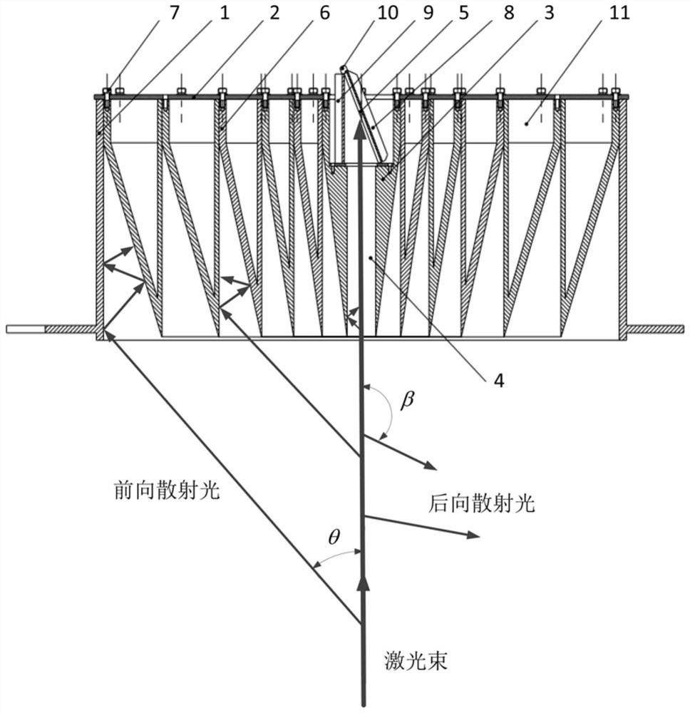
[0022] Such as figure 1 , 2 As shown, a kind of laser direct light and its forward scattered light light trapping device include an annular shell 1, a circular cover plate 2 is connected to the upper end of the annular shell 1, and the vertical center of the inner side of the circular cover plate 2 A light-transmitting plate 3 is fixed, a light-through hole 4 is opened at the center of the light-through plate 3, a through-hole communicating with the light-through hole 4 is opened at the center of the circular cover plate 2, and a light-through hole 4 is provided inside the upper end of the light-through hole 4. Steps, black glass 5 and cooling fins are provided at the steps of the light hole, and a plurality of annular hollow cones 6 are fixed on the inner side of the circular cover plate 2, and the plurality of annular hollow cones 6 are nested on the outside of the light-transmitting plate 3 in turn .

[0023] The upper ends of the hollow cone 6 and the light-transmitting ...


PUM

PropertyMeasurementUnit
surface roughnessaaaaaaaaaa
diameteraaaaaaaaaa

Abstract

The invention discloses a laser direct light and its forward scattered light trapping device, which comprises an annular casing, a circular cover is connected to the upper end of the annular casing, and a through hole is vertically fixed at the center of the inner side of the circular cover. The light plate has a light hole in the center of the light plate, a through hole communicating with the light hole in the center of the circular cover plate, a step is provided on the inner side of the upper end of the light hole, and at the step of the light hole Black glass and cooling fins are provided, and a plurality of annular hollow cones are fixed on the inside of the circular cover plate, and the plurality of annular hollow cones are nested on the outside of the light-transmitting plate in turn. The invention uses multiple cones to reflect the incident light back and forth in the light trap multiple times to achieve the purpose of extinction, and has the characteristics of large opening diameter, small overall size and weight, and strong extinction ability.

Description

technical field [0001] The invention relates to the technical field of stray light suppression, in particular to a laser direct light and its forward scattered light optical trap device. Background technique [0002] The measurement of light scattering characteristics of aerosol particles is one of the prerequisites for improving the accuracy of atmospheric aerosol remote sensing. Due to its good monochromaticity, high brightness and small divergence angle, laser is often used as the light source of the instrument for measuring the light scattering characteristics of particles. The angle-integrated intensity of light scattered by aerosol particles is usually only 10 of that of the light source. -4 For particles with a larger particle size (equal to or larger than the wavelength of the light source), the intensity of forward scattered light is often orders of magnitude higher than that of backscattered light. This leads to the fact that the closed particle scattering measur...

Claims


Application Information

Patent Timeline
Patent Type & Authority Patents(China)
IPC IPC(8): G02B27/00G01N21/49
Inventor 胡强裘桢炜崔卫华洪津常钰阳
Owner HEFEI INSTITUTES OF PHYSICAL SCIENCE - CHINESE ACAD OF SCI
Learn More