K/Ka dual-band common-aperture antenna array

A dual-band, common-aperture technology, applied in the field of two-dimensional large-angle scanning phased array antennas, can solve the problems of high profile, low application frequency, unfavorable low-profile conformal application, etc., and achieve simple feeding structure and structure compact effect

Inactive Publication Date: 2019-06-18
10TH RES INST OF CETC
View PDF11 Cites 22 Cited by
  • Summary
  • Abstract
  • Description
  • Claims
  • Application Information

AI Technical Summary

Problems solved by technology

At present, in the common-aperture antenna arrays with K/Ka or similar frequency ratios at home and abroad, the single-layer array cannot fully meet the grating lobe conditions of the two-dimensional large-angle scanning of the phased array antenna.
However, when the stacked and three-dimensional array subunits are used, although the grating lobe conditions can be met, the section height is increased, which is extremely unfavorable for low-profile conformal applications, and the RCS is high, which cannot meet the requirements of low RCS.
[0003] Chinese patent application CN201310538063.8 discloses a dual-frequency dual-circular polarization common-aperture antenna array for two-dimensional phased array scanning, which adopts square radiators in the same layer, but the metal radiators in the Ku frequency band in the central area If the spacing is greater than 0.5 times

Method used


Image

  • K/Ka dual-band common-aperture antenna array
  • K/Ka dual-band common-aperture antenna array

Examples


Embodiment Construction

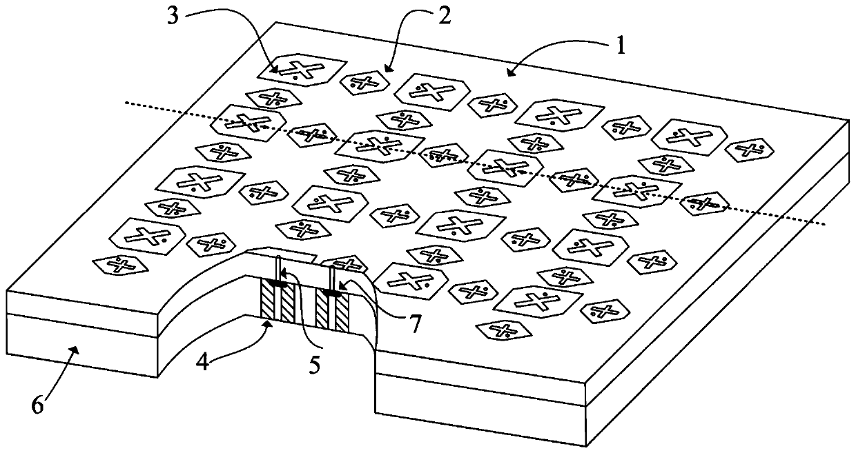
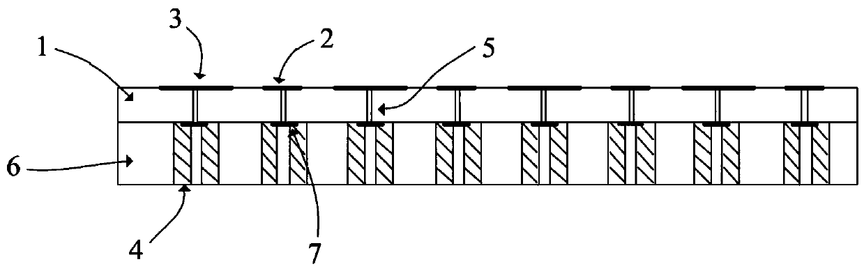
[0016] refer to figure 1 , figure 2 . In a best implementation example described below, the K / Ka dual-band co-aperture antenna array includes: overlapping and fixed dielectric substrate 1 and metal base plate 6, Ka frequency patch 2, K frequency patch 3, and feeding Shaft 4 , feed post 5 , and pad 7 . On the dielectric substrate 1, there are K-band patches 3 divided into uniform rectangular arrays, and Ka-band patches 2, Ka-band patches 2, and K-band patches interspersed in the center of the K-band patch 3 in the form of interpolation. The patches 3 are respectively orthogonally connected to the pads 7 located on the bottom surface of the dielectric substrate 1 through the feed posts 5 penetrating the dielectric substrate 1. The pads 7 are connected to the feed coaxial 4, and the feed coaxial 4 passes through the metal base plate 6 and solders. Disc 7 is connected to feed power in a touch-connected manner.

[0017] The Ka-band patch and the K-band patch are printed on the...


PUM


Abstract

The invention discloses a K/Ka dual-band common-aperture antenna array, aiming to provide an antenna array surface capable of reducing the antenna profile, covering K and Ka bands and sharing a dual-band aperture. The invention is implemented by the following technical schemes: K-band patches are distributed on a dielectric substrate in the form of a uniform rectangular array, Ka-band patches areinterspersed in the center of the interval of adjacent K-band patches in an interpolation manner, the K-band patches are in orthogonal connection with a bonding pad located on the bottom surface of the dielectric substrate through a feeder pillar that penetrates through the dielectric substrate, the bonding pad is connected with a coaxial feeder, and the coaxial feeder penetrates through a metal base plate to connect with the bonding pad and feeds in a touch-type connection manner, wherein the K-band patches are combined with the metal base plate through the feeder pillar to form a K-band antenna array surface, the feeder pillar is connected with the coaxial feeder through the bonding pad to form a K-band channel; and the Ka-band patches are combined with the metal base plate through the feeder pillar to form a Ka-band antenna array surface, and the feeder pillar and the bonding pad conduct the coaxial feeder to form a Ka-band channel.

Description

technical field [0001] The invention relates to a K / Ka dual-band common-aperture antenna array, in particular, it is suitable for constructing a K / Ka common-aperture two-dimensional large-angle scanning phased array antenna array. Background technique [0002] In the phased array antenna system with limited size and weight, in order to reduce the volume and RCS of the system, it is urgent to reduce the aperture of the antenna as much as possible without affecting the performance of the antenna. If antennas of different frequency bands are integrated into a unified aperture, the antenna aperture can be greatly reduced. At present, in the common-aperture antenna arrays with K / Ka or similar frequency ratios at home and abroad, the single-layer array cannot fully meet the grating lobe conditions of the two-dimensional large-angle scanning of the phased array antenna. However, when stacked and three-dimensional array subunits are used, although the grating lobe conditions can be...

Claims


Application Information

Patent Timeline
IPC IPC(8): H01Q1/36H01Q1/38H01Q1/50H01Q21/00
Inventor 陆晟晨何小峰孙凤林尹继亮王军会
Owner 10TH RES INST OF CETC
Why Eureka
Try Eureka