

Refection type liquid crystal display device
A liquid crystal display device, reflective technology, applied in static indicators, instruments, optics, etc., can solve problems such as brightness reduction
- Summary
- Abstract
- Description
- Claims
- Application Information
AI Technical Summary
Problems solved by technology
Method used
Image

Examples
example 1
[0058] Figure 6 It is a cross-sectional view of a reflective liquid crystal display device 30 according to Example 1 of the present invention. The TFT 40 is formed on the substrate 31 by a known technique. Concave and convex organic insulating films 42a and 42b are also formed on the substrate 31, and the reflective electrode 38 is thus formed so as to be electrically connected to the respective TFT 40 through the contact hole 43. An alignment film 44 is formed on the obtained substrate 31.
[0059] The color filter 46 is formed on the facing substrate 45. The color filter 46 includes red, green, and blue color filters 46a and a black color filter 46b, wherein the color filter 46a is located at a position corresponding to the reflective electrode 38 on the substrate 31, and the color filter 46b is not corresponding to the reflection The remaining position of the electrode 38. A protective film (not shown in the figure) is formed on the entire surface of the color filter 46. It i...
example 2
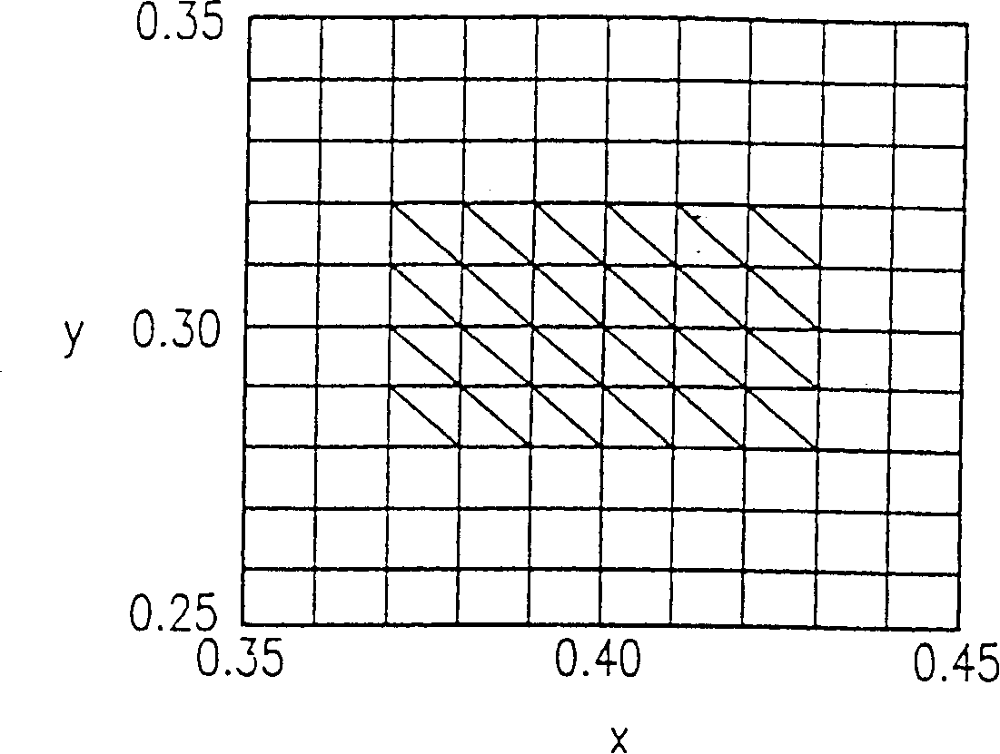
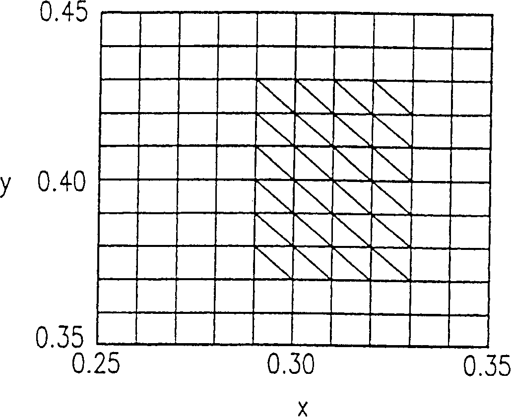
[0074] The reflective liquid crystal display device of Example 2 has substantially the same structure as the reflective liquid crystal display device described in Example 1. In this example, the red color filter used in Example 1 is used, and the spectral characteristics of the green and blue color filters are set so that the white color obtained by the additional color mixing of the three colors is in the XYZ color system The chromaticity coordinates (x, y) are in Figure 5 In the range shown by the diagonal line in, that is, the expressions 0.28≤x≤0.31 and 0.29≤y≤0.33 are satisfied. In addition, if the y value of the three stimulated values in the XYZ color system is in the range of 50 to 70 (including 50 and 70), sufficient brightness can be obtained.
[0075] We know that since the color filter used in the liquid crystal display device includes a layer formed of a transparent conductive film, a protective film, etc., made of materials such as ITO, the white color is particul...
example 3
[0081] Generally, the color reproduction range of a liquid crystal display device is determined by the color purity of the color filter. When the color purity is higher, the color reproduction range becomes larger. However, when the color purity is high, the light transmittance of the color filter becomes low, and bright display cannot be realized. Therefore, in this example, when designing the color of the red, green, and blue color filters 46a, priority is given to the display brightness. The structure of the reflective liquid crystal display device of this example is substantially the same as the structure of the reflective liquid crystal display device of Example 1.
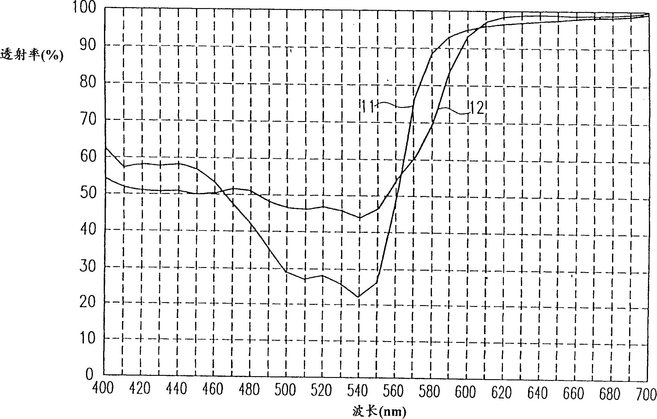
[0082] When increasing the transmittance while maintaining a certain chromaticity to a certain extent, when displaying colors such as green, yellow, and blue-green that include many wavelength ranges with luminous effects, they exhibit extremely poor contrast to white. It is the most difficult to recognize. For t...
PUM
 Abstract
Description
Claims
Application Information