Charging-discharging control method and system for energy storage units in distributed energy storage direct current microgrid

A technology of DC microgrid and distributed energy storage, which is applied in the direction of parallel operation of DC power supplies, electrical components, battery circuit devices, etc., can solve the problems of short life of the state of charge energy storage unit, achieve improved life, fast and accurate balance , Guarantee the effect of line voltage

Active Publication Date: 2019-06-18
STATE GRID XINJIANG ELECTRIC POWER CO ECONOMIC TECH RES INST +3
View PDF1 Cites 12 Cited by
  • Summary
  • Abstract
  • Description
  • Claims
  • Application Information

AI Technical Summary

Problems solved by technology

[0005] The invention provides a method and system for controlling the charging and discharging of energy storage units in a distributed energy storage DC microgrid, which is used to solve the problem of energy storage caused by the unbalanced state of charge value of each energy storage unit in the existing droop control method. Problems with short unit life

Method used


Image

  • Charging-discharging control method and system for energy storage units in distributed energy storage direct current microgrid
  • Charging-discharging control method and system for energy storage units in distributed energy storage direct current microgrid
  • Charging-discharging control method and system for energy storage units in distributed energy storage direct current microgrid

Examples


Embodiment 1

[0044] A charging and discharging control method for an energy storage unit in a distributed energy storage DC microgrid. In the discharging phase, the controller corresponding to the pth energy storage unit controls its discharge, and the controller corresponding to the qth energy storage unit controls its discharge. , and when SOC p >SOC q When , the discharge current controlled by the controller corresponding to the pth energy storage unit is greater than the discharge current controlled by the controller corresponding to the qth energy storage unit; in the charging stage, the controller corresponding to the pth energy storage unit Control its charging, the controller corresponding to the qth energy storage unit controls its charging, and when SOC p >SOC q , the charging current controlled by the controller corresponding to the pth energy storage unit is greater than the charging current controlled by the controller corresponding to the qth energy storage unit; where p an...

Embodiment 2

[0067] On the basis of embodiment one, the governing equation is: u dcj = u dcref -K j i dcj ·G j + r j i dcj , where r j Indicates the line impedance corresponding to the jth energy storage unit.

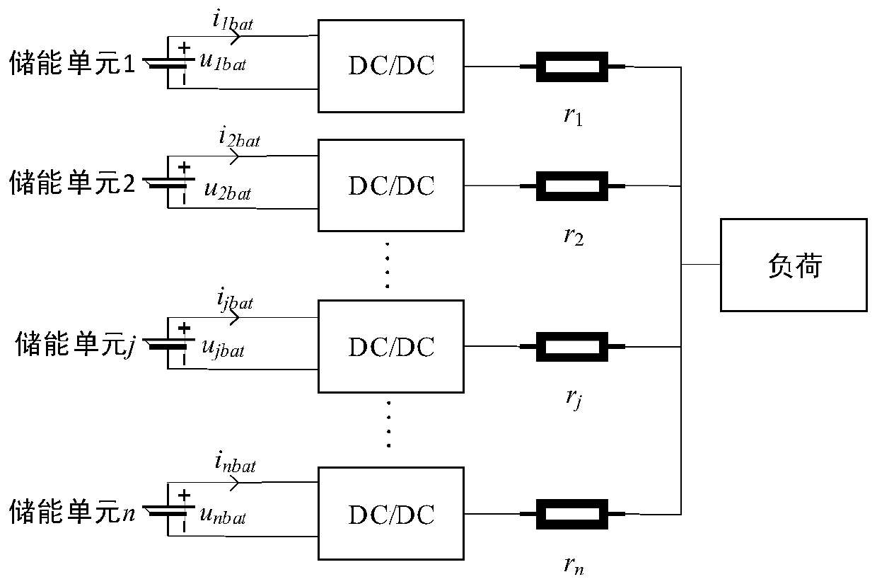
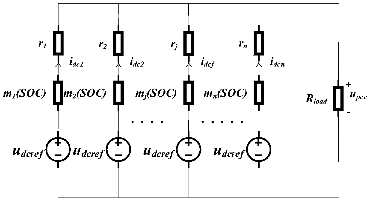
[0068] For example, figure 1 The power system in is simplified to get figure 2 ,Such as figure 2 As shown, n voltages are u dcref The power supply passes through the resistance m j (SOC) and r j The impedances are connected in parallel with each other, while giving an impedance of R load The resistor power supply, u pcc is the common point voltage, i dcj For the jth energy storage unit, the resistance is m j The output current output by the resistance of (SOC) can be obtained from the circuit relationship:

[0069]

[0070] The subscript j represents the relevant variable of the jth energy storage unit, such as i dcj Represents the output current of the jth energy storage unit, R s is the parallel impedance, and n represents the total number of energy storage...

Embodiment 3

[0092] A charging and discharging control system for energy storage units in a distributed energy storage DC microgrid, including: controllers corresponding to all energy storage units in the distributed energy storage DC microgrid; The controller controls its discharge, and the controller corresponding to the qth energy storage unit controls its discharge, and when the SOC p >SOC q , the discharge current controlled by the controller corresponding to the pth energy storage unit is greater than the discharge current controlled by the controller corresponding to the qth energy storage unit; in the charging stage, the pth energy storage unit corresponds to The controller controls its charging, and the controller corresponding to the qth energy storage unit controls its charging, and when the SOC p >SOC q , the charging current controlled by the controller corresponding to the pth energy storage unit is greater than the charging current controlled by the controller correspondin...


PUM


Abstract

The invention relates to a charging-discharging control method and system for energy storage units in a distributed energy storage direct current microgrid. A balance factor is introduced in a controlequation; in a discharging stage, the energy storage unit with the relatively high SOC outputs a relatively high discharging current, and the energy storage unit with the relatively low SOC needs torelease relatively low electricity; and in a charging stage, a charging current of the energy storage unit with the relatively high SOC needs to be maintained at a relatively low level, and the energystorage unit with the relatively low SOC needs to obtain a relatively high charging current, so that the purpose of balancing the SOC of different energy storage units is achieved. The SOC-based balance factor is introduced in an original droop coefficient, so that the charging-discharging conditions of the energy storage units are continuously adjusted along with the SOC values of the energy storage units, the purpose of rapidly balancing the SOC of the energy storage units is achieved, rapid balance of the SOC of the energy storage units can be realized, and the service life of each energystorage unit is prolonged.

Description

technical field [0001] The invention relates to the technical field of energy storage control of micro-dot grids, in particular to a charging and discharging control method and system for an energy storage unit in a distributed energy storage DC micro-grid. Background technique [0002] At present, with the prominence of environmental problems and the enhancement of human awareness of environmental protection, renewable distributed power sources such as photovoltaics and wind turbines, which have the advantages of cleanliness, renewability, and on-site consumption, have developed rapidly. Energy has become a research hotspot. [0003] Through grid-connected converters, distributed power sources such as photovoltaics and wind turbines can be connected to the DC grid in parallel. However, due to the volatility, intermittent and unstable characteristics of most distributed power sources in microgrids, it is necessary to realize large-scale distributed power generation. In orde...

Claims


Application Information

Patent Timeline
Patent Type & Authority Applications(China)
IPC IPC(8): H02J1/10H02J7/34
Inventor 曹新慧刘昱良晁凯云苗世洪刘子文车勇张伟李忠政李娟周二彪华东栗磊赫嘉楠
Owner STATE GRID XINJIANG ELECTRIC POWER CO ECONOMIC TECH RES INST
Why Eureka
Try Eureka