
Mechanical arm obstacle avoidance method based on multiple sensors, and mechanical arm

A multi-sensor, robotic arm technology, used in manipulators, program-controlled manipulators, manufacturing tools, etc., to achieve high obstacle avoidance accuracy, avoid local minimum problems, and high analysis accuracy.

Pending Publication Date: 2019-06-21
QILU UNIV OF TECH
View PDF0 Cites 14 Cited by
  • Summary
  • Abstract
  • Description
  • Claims
  • Application Information

AI Technical Summary

Problems solved by technology

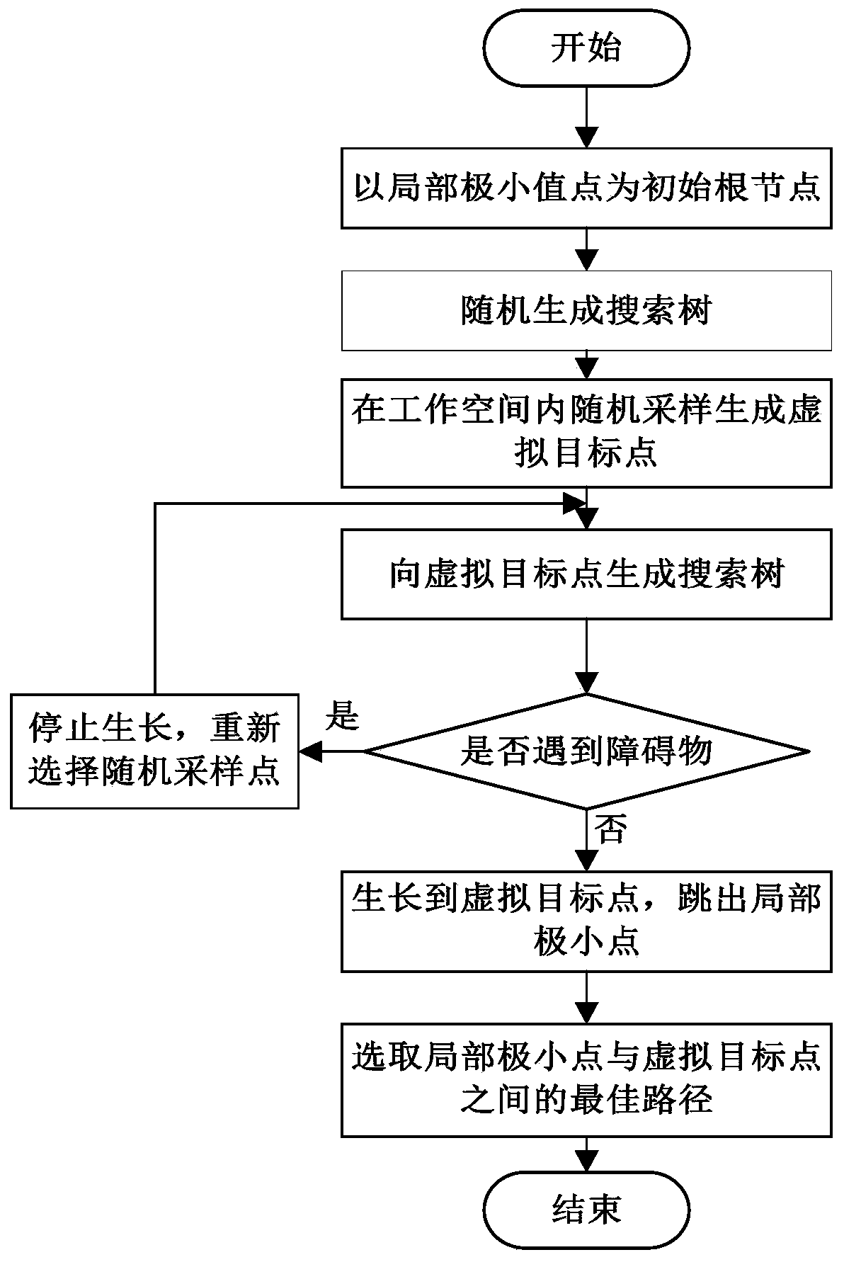
[0003] In order to overcome the deficiencies of the above-mentioned prior art, the present invention provides a method for grabbing glass slides with a multi-sensor-based robotic arm without collision, combining visual sensors and laser sensors to detect obstacles in the environment, and using grid maps Carry out fusion to complete the motion planning of the manipulator, aiming at the shortcomings of the artificial potential field method, combined with the RRT algorithm to improve

Method used


Image

  • Mechanical arm obstacle avoidance method based on multiple sensors, and mechanical arm
  • Mechanical arm obstacle avoidance method based on multiple sensors, and mechanical arm
  • Mechanical arm obstacle avoidance method based on multiple sensors, and mechanical arm

Examples


Embodiment 1

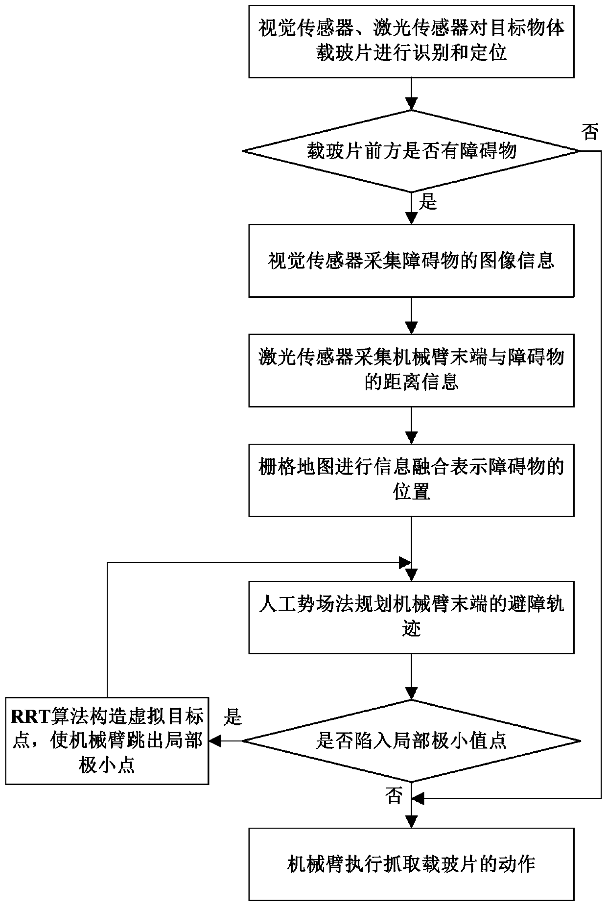
[0057] This embodiment discloses a multi-sensor based robotic arm for grabbing slides, one or more laser sensors and a vision sensor are installed at the end of the mechanical arm, the one or more laser sensors and The vision sensors all send the collected signals to the central processing unit, and the central processing unit analyzes the path of the manipulator based on the above signals, generates control signals and sends them to the controller, so as to control the movement of the manipulator according to the planned path.

[0058]If there is only one laser sensor, it should be located directly above or directly below the visual sensor, and as close as possible to the visual sensor; Above or directly below, as close as possible to the vision sensor, to ensure that the distance measured by the laser sensor to the obstacle in front is approximately equal to the distance to the obstacle in the image acquired by the vision sensor, what you see is what you get.

[0059] The ce...

Embodiment 2

[0084] The purpose of this embodiment is to provide a multi-sensor based robot arm obstacle avoidance method for grasping slides, using the robot arm as described in the first embodiment.

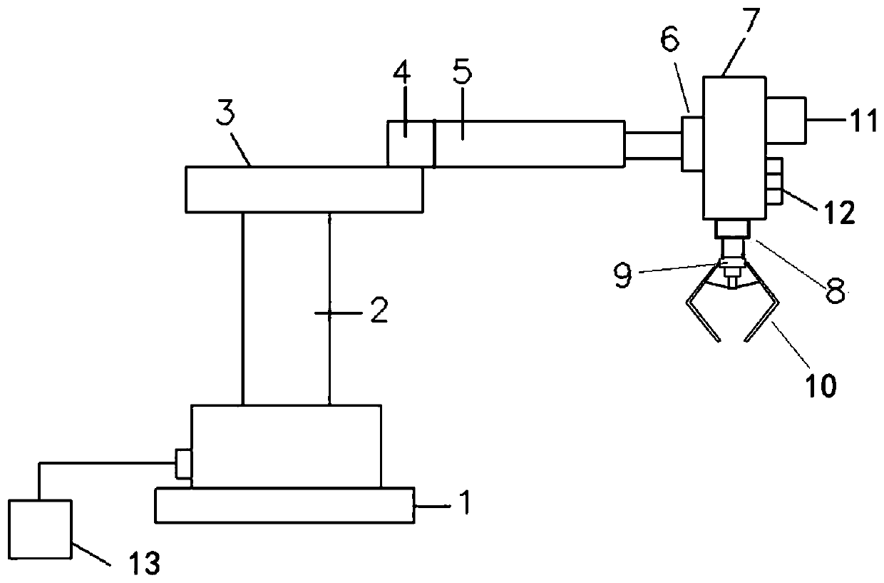
[0085] In this embodiment, a three-stage mechanical arm is used, such as image 3 As shown, it includes a base 1, the base 1 is provided with a support shaft 2, which is connected to the base 1 in rotation, the upper part of the support shaft 2 is fixedly connected with one end of the first arm 3, and the other end of the first arm 3 is connected with the first connecting part 4 Rotationally connected, the first connecting part 4 is fixedly connected to one end of the second arm 5, specifically, the second arm 5 is a telescopic hydraulic cylinder, one end of the cylinder body is fixedly connected to the first connecting part 4, and one end of the piston rod passes through the second arm. Two connecting parts 6 are connected with the third arm 7, and the end face of the other end of the thir...


PUM


Abstract

The invention discloses a mechanical arm obstacle avoidance method based on multiple sensors and a mechanical arm. The method comprises the steps that the surrounding information of an target object is obtained on the basis of one or more laser sensors and visual sensors; whether an obstacle exists between the tail end of the mechanical arm and the target object is judged; if the obstacle exists,the position of the obstacle is primarily positioned on the basis of image information; the actual distance information of the tail end of the mechanical arm and the obstacle is collected through theone or more laser sensors; a raster map is built according to the primary positioning result and the actual distance information collected by the laser sensors; and on the basis of the raster map, a path is planned through a method for combining manual potential field and a rapid exploring random tree, and the mechanical arm is controlled to get close to the target object. The obstacle in the environment is detected through combination of the visual sensors and the laser sensors, and the obstacle avoidance precision is high.

Description

technical field [0001] The invention belongs to the technical field of mechanical arm motion planning, and in particular relates to a multi-sensor based obstacle avoidance method for a mechanical arm and a mechanical arm. Background technique [0002] The mechanical arm is the most widely used automation device in the field of robotics. In the traditional production process, the grasping, handling, and installation of the workpiece are all done manually. The production efficiency is low, the work is dangerous, and the labor cost is high. High strength, high turnover rate of operators. In order to solve the above problems, in the prior art, a mechanical arm is used to complete the above operations. The motion planning of the manipulator means that in an environment with obstacles, the manipulator finds a collision-free trajectory from the initial state to the final state according to a given method. Therefore, the robotic arm may encounter obstacles during its movement. At...

Claims


Application Information

Patent Timeline
Patent Type & Authority Applications(China)
IPC IPC(8): B25J9/16
Inventor 李庆华沐雅琪王喆
Owner QILU UNIV OF TECH
Learn More