
Spraying structure for hydraulic machining

A hydraulic and spray head technology, applied in the field of hydraulic processing, can solve problems such as uncompact combination of components, small adjustable nozzle angle, scratches on the workpiece surface, etc., so as to prevent the loss of components and the difficulty of replacing accessories, and increase the front and rear Mobility, powerful spray effect

Inactive Publication Date: 2019-06-21
东莞市中帆新材料科技有限公司
View PDF7 Cites 2 Cited by
  • Summary
  • Abstract
  • Description
  • Claims
  • Application Information

AI Technical Summary

Problems solved by technology

[0003] However, the injection structure for hydraulic machining currently on the market has scattered nozzles, inconvenient replacement, relatively small and simple operating table, small adjustable angle of nozzles, relatively single types of nozzles, large application limitations, uncompact combination of components, and long service life. Short, moreover, the current hydraulic machining is generally adding particles in water, such as corundum, abrasive grains, etc., which will cause problems such as scratches on the surface of the workpiece, while pure water machining will require higher water pressure, which will affect the processing efficiency

Method used


Image

  • Spraying structure for hydraulic machining
  • Spraying structure for hydraulic machining
  • Spraying structure for hydraulic machining

Examples


Embodiment Construction

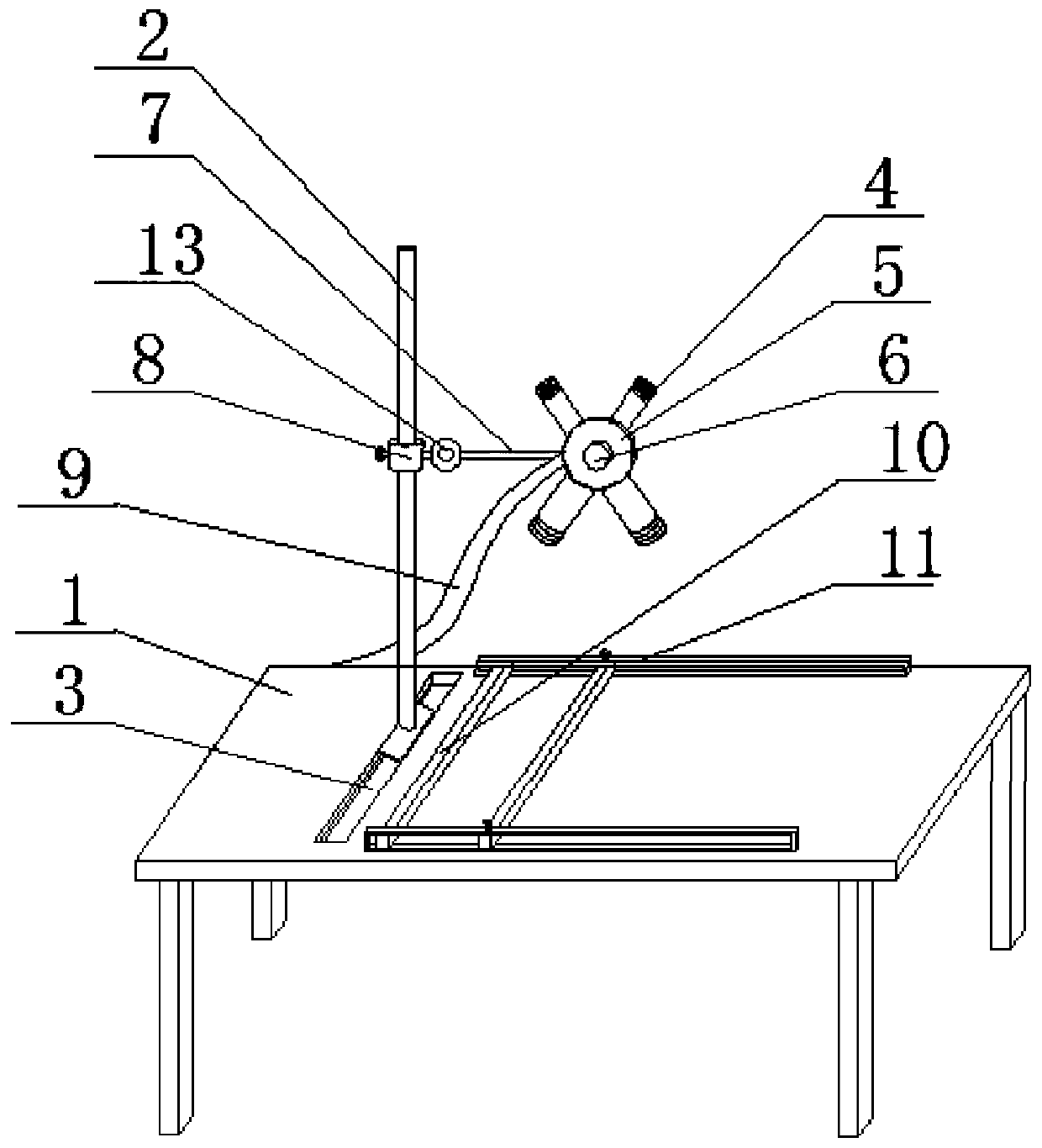
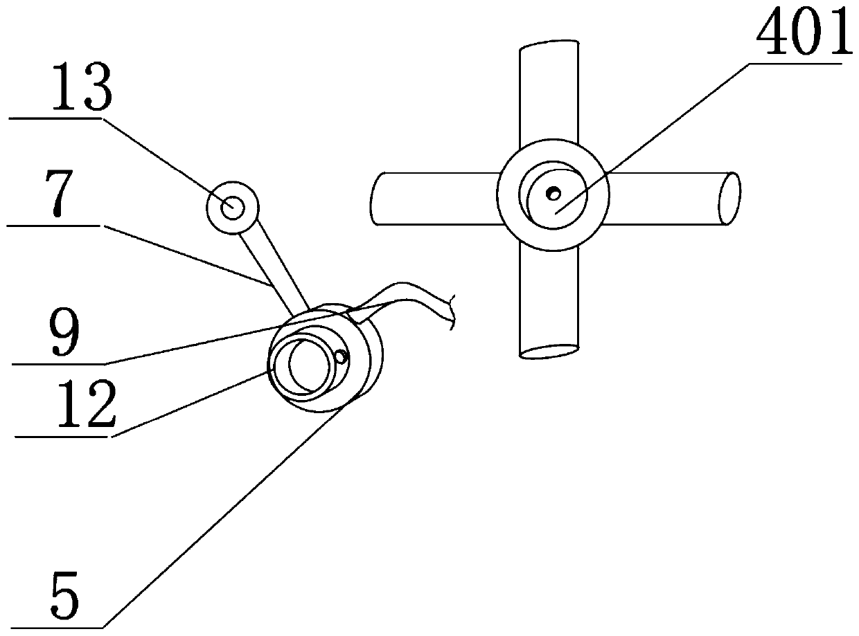
[0031] see Figure 1~4 , in an embodiment of the present invention, an injection structure for hydraulic machining, including an operation table 1, a pressure chamber 5 and an injection head 4, wherein the pressure chamber 5 is arranged on the operation table 1 so as to be movable laterally, and The pressure chamber 5 can be adjusted up and down in the vertical direction, and the pressure chamber 5 is a disc-shaped structure, which is characterized in that,

[0032] The replaceable connection on the pressure chamber 5 is provided with a plurality of spray heads 4, and each spray head 4 is arranged at intervals along the circumference of the pressure chamber 5; the diameter of the spray hole in each of the spray heads 4 is different;

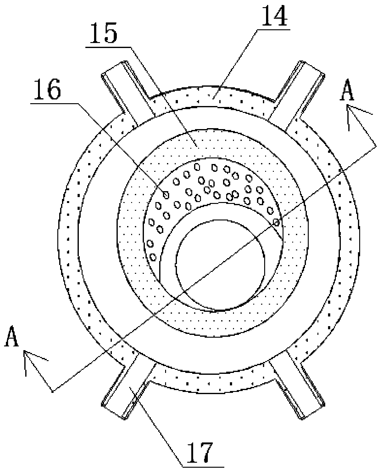
[0033] The inside of the pressure chamber 5 is coaxially provided with an outer water jacket 14, and the inside of the outer water jacket is eccentrically provided with an air hole sleeve 15, between the inner wall of the outer water jacket 14 a...


PUM


Abstract

The invention discloses a spraying structure for hydraulic machining. The spraying structure is used for cutting in a manner of mixing bubbles with water, the bubbles are attached to water before being sprayed, when the water is impacted on the surface of a workpiece, the bubbles are instantly broken, and the efficiency of workpiece machining is improved; due to the bubbles flow in the water, thesurface quality and smoothness of the machined surface are ensured, and the machining quality is improved meanwhile the machining efficiency is ensured; an air hole sleeve is eccentrically arranged inan outer water jacket, through the eccentric arrangement, air flow and liquid flow in the outer water jacket can automatically flow towards each other due to the fact that the eccentric inner space is not uniform, so that the combination performance of the air bubbles and water is improved; through the conical design of the air hole sleeve and the sleeve connection structure of the outer water jacket, the stability and the mixing effect of machining can be effectively ensured, and the spraying machining efficiency is ensured; and moreover, a plurality of spraying heads are arranged, and the spraying heads with spraying holes of different diameter can be used for machining, so that the structure is convenient and simple.

Description

technical field [0001] The invention relates to the technical field of hydraulic machining, in particular to a spray structure for hydraulic machining. Background technique [0002] Harnessing the kinetic energy of liquid jets for cutting has been around for decades. This process usually makes the fluid flow from a nozzle with a diameter of 0.05 to 0.4mm (such nozzles are often made of artificial sapphire, diamond or corundum, etc., and their service life can reach 200 to 500h) under a pressure of 70 to 500 MPa. It is ejected at a supersonic speed of 300-1000m / s. The strong force of this jet can cause the processed material to break with the separation of its layer-by-layer particles. During this process, the kinetic energy of the jet is converted into hydraulic cutting. [0003] However, the injection structure for hydraulic machining currently on the market has scattered nozzles, inconvenient replacement, relatively small and simple operating table, small adjustable ang...

Claims


Application Information

Patent Timeline
Patent Type & Authority Applications(China)
IPC IPC(8): B26F3/00B26D7/02
Inventor 李洪洋虞松
Owner 东莞市中帆新材料科技有限公司
Learn More