A three-dimensional matrix storage system

A three-dimensional matrix and storage system technology, applied in the field of storage, can solve the problems of long storage and retrieval time, complex storage structure, and low storage density, and achieve the effect of high space utilization, high storage density, and simple structure

Inactive Publication Date: 2020-10-09
SHENYANG INST OF AUTOMATION - CHINESE ACAD OF SCI
View PDF5 Cites 0 Cited by
  • Summary
  • Abstract
  • Description
  • Claims
  • Application Information

AI Technical Summary

Problems solved by technology

[0003] In view of the above problems, the purpose of the present invention is to provide a three-dimensional matrix storage system to solve the existing problems of complex storage structure, high cost, low storage density, and long storage and retrieval time

Method used


Image

  • A three-dimensional matrix storage system
  • A three-dimensional matrix storage system
  • A three-dimensional matrix storage system

Examples


Embodiment 1

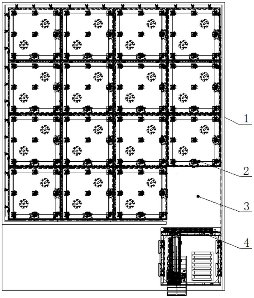
[0047] The selective entry and exit process of the transfer platform 2 numbered 01 in the warehouse along the two-dimensional plane coordinates is as follows:

[0048] There is a vacancy at the entrance and exit of the warehouse, above the transfer platform 2 numbered 01 is the transfer platform 2 numbered 05 and 08, as shown in Figure 8(a); the transfer platform 2 numbered 05 and 08 The platform 2 moves in the direction of the entrance and exit of the warehouse, leaving a space above the transfer platform 2 numbered 01, as shown in Figure 8(b); the transfer platform 2 numbered 01 moves upward to the upper space, as shown in Figure 8 As shown in (c); transfer platforms 2 numbered 02 and 11 move right to the space below transfer platform 2 numbered 01, as shown in Figure 8(d); transfer platform 2 numbered 05 Move to the vacant position, as shown in Figure 8(e); the transfer platforms 2 numbered 08 and 01 move to the left to enter and exit the warehouse, as shown in Figure 8(f);...

Embodiment 2

[0050] The transfer platform 2 numbered 05, 08, and 10 in the warehouse arrives at the warehouse entrance in sequence, and the process is as follows:

[0051] There is a space at the entrance and exit of the warehouse, and the transfer platforms 2 numbered 05, 08, and 10 are located on the side of the entrance and exit, as shown in Figure 9(a); the transfer platforms 2 with numbers 05, 08, and 10 Move to the left to the entrance and exit of the warehouse, as shown in Figure 9(b); the transfer platform 2 numbered 04 moves up to the empty position, as shown in Figure 9(c); the transfer platform 2 numbered 02, 11, and 01 Platform 2 moves to the right to the vacancy, as shown in Figure 9(d); the transfer platform 2 numbered 05 moves down to the vacancy, as shown in Figure 9(e); the transfer platforms numbered 08, 10, and 04 2 moves to the left to the entrance and exit of the warehouse, as shown in Figure 9 (f); the transfer platform 2 numbered 01 moves up, and the transfer platfor...


PUM


Abstract

The present invention belongs to the technical field of storage, and particularly relates to a three-dimensional matrix-type storage system. The three-dimensional matrix-type storage system comprises a computer management system, a matrix-type repository and a plurality of movable carrier platforms arranged in the matrix-type repository. The plurality of movable carrier platforms are arranged in the form of a two-dimensional matrix to form a digital Huarong Dao mode; two adjacent movable carrier platforms can slide relative to each other in a contact manner; and stacking can be performed on an upper portion of each movable carrier platform to form a three-dimensional matrix, and there is always a vacancy in the three-dimensional matrix to serve as a space for enabling the movable carrier platform to move. A cargo entrance / exit is provided in an end of the matrix-type repository, and the computer management system is used for controlling a specified movable carrier platform to move, in a parallel manner, towards the cargo entrance / exit along two-dimensional plane coordinates, thereby realizing the entering and leaving of cargo. The present invention is high in storage density and utilization rate of space, and related devices are simple in structural form and low in cost, and has a high practicability.

Description

technical field [0001] The invention belongs to the technical field of storage, in particular to a three-dimensional matrix storage system. Background technique [0002] At present, in the field of warehousing, it often occurs that the storage space is limited, and there are many types and quantities of goods, and the storage and withdrawal of goods cannot be completed effectively and in time. Its external performance is fixed storage of goods. Cargo transport vehicles include AGV, RGV, stacking manipulator, forklift (manual), etc. to store goods. The logistics takes a long time, and there are complex storage space structures, high costs, and low storage density. question. Contents of the invention [0003] In view of the above problems, the object of the present invention is to provide a three-dimensional matrix storage system to solve the existing problems of complex structure, high cost, low storage density and long time to store and retrieve goods. [0004] In order ...

Claims


Application Information

Patent Timeline
Patent Type & Authority Patents(China)
IPC IPC(8): B65G1/04B65G1/137
CPCB65G1/04B65G1/137
Inventor 陈书宏罗浩然马克林魏宏宇许胜利
Owner SHENYANG INST OF AUTOMATION - CHINESE ACAD OF SCI
Why Eureka
Try Eureka