
A feed mechanism for a biomass fuel furnace

A technology of biomass fuel and feeding mechanism, which is applied in the directions of fuel supply, combustion of solid fuel, combustion method, etc., can solve the problem of inconvenient feeding of biomass fuel furnace, and achieve the effect of saving manpower

Active Publication Date: 2020-10-16
浏阳市三工环保科技有限公司
View PDF9 Cites 0 Cited by
  • Summary
  • Abstract
  • Description
  • Claims
  • Application Information

AI Technical Summary

Problems solved by technology

[0005] The purpose of the present invention is to provide a biomass fuel furnace feeding mechanism that can automatically feed materials according to the temperature in the furnace to solve the problem of inconvenient feeding of existing biomass fuel furnaces

Method used


Image

  • A feed mechanism for a biomass fuel furnace
  • A feed mechanism for a biomass fuel furnace
  • A feed mechanism for a biomass fuel furnace

Examples


Embodiment 1

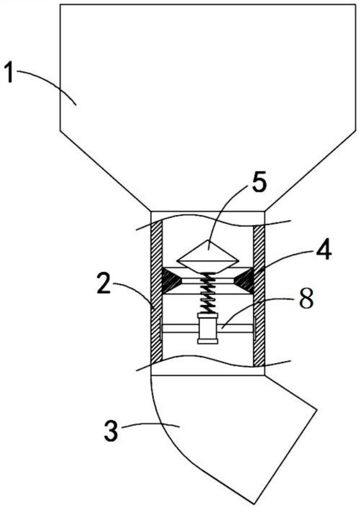
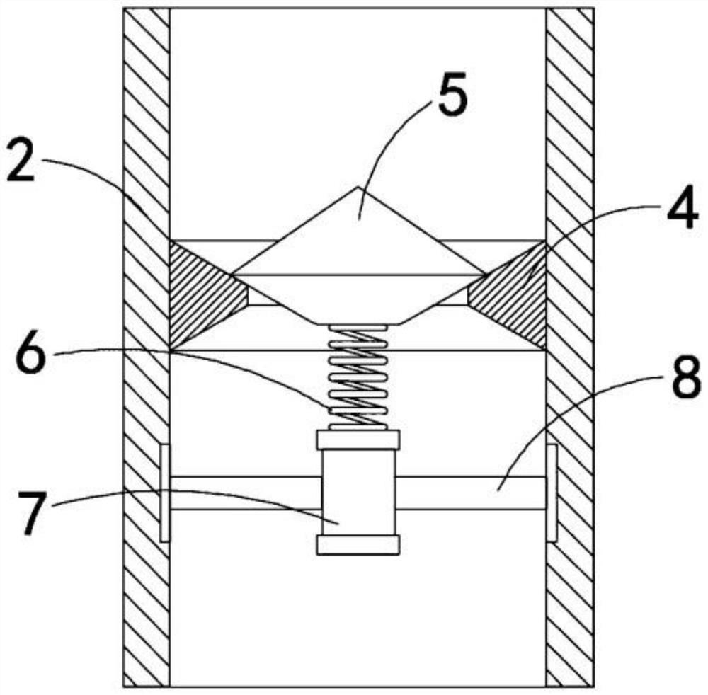
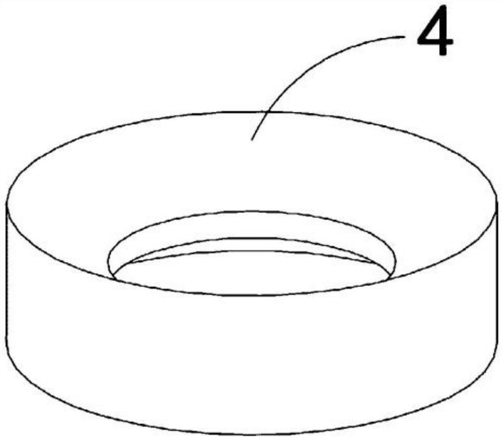
[0025] Such as Figure 1-4 As shown, a biomass fuel furnace feeding mechanism includes a feed hopper 1, the lower end of the feed hopper 1 is fixedly connected with a vertical pipe 2, the lower end of the vertical pipe 2 is fixedly connected with an inclined pipe 3, and the vertical pipe 2 is fixedly connected with There is a sealing ring 4, the upper end of the sealing ring 4 is recessed downwards and is set in a bowl shape, which can play a gathering effect and make it easier for fuel to enter the sealing ring 4. It is worth mentioning that the lower end of the sealing ring 4 is recessed upwards to form a bowl The seal ring 4 is provided with a matching seal block 5 directly above the seal ring 4, and the lower end of the seal block 5 is set in a downwardly protruding conical shape. When the seal block 5 When the lower end of the sealing block 5 is attached to the upper end of the sealing ring 4, the fuel in the feed hopper 1 can be blocked from the outside of the vertical p...

Embodiment 2

[0031] Such as Figure 5-6 As shown, the difference between this embodiment and Embodiment 1 is that the memory spring 6 is covered with a bellows 9 that expands and contracts along its axis, and the bellows 9 is made of heat-resistant rubber. Better materials such as metal, etc., the upper and lower ends of the bellows 9 are respectively fixed and sealed with the lower end surface of the sealing block 5 and the upper end surface of the connecting seat 7, and the end of the connecting rod 8 away from the connecting seat 7 is set through the vertical pipe 2. The rod 8 is hollow, and the connecting seat 7 is provided with an air delivery hole that penetrates up and down. The upper end of the air delivery hole communicates with the bellows 9, and the connecting rod 8 communicates with the air delivery hole. One-way valve 10, the lower end of connecting seat 7 is fixedly connected with second one-way valve 11, specifically, first one-way valve 10 allows gas to enter the air delive...


PUM


Abstract

The invention belongs to the field of biomass energy conversion, and particularly relates to a biomass fuel furnace feeding mechanism comprising a feeding hopper. The lower end of the feeding hopper is fixedly connected with a vertical pipe, the lower end of the vertical pipe is fixedly connected with a diagonal pipe, a sealing ring is fixedly connected into the vertical pipe, the upper end of thesealing ring is recessed downwards to be arranged in a bowl shape, a sealing block matched with the sealing ring is arranged over the sealing ring, and the lower end of the sealing block is in a round table shape protruding downwards; and the lower end of the sealing block is fixedly connected with a memory spring, the lower end of the memory spring is fixedly connected with a connecting seat, and the connecting seat is fixedly connected to the inner side wall of the vertical pipe through a plurality of connecting rods. According to the biomass fuel furnace feeding mechanism, it can determinethat there is not much fuel remaining in a fuel furnace through the change of the temperature of the position, close to the feeding mechanism, in the fuel furnace, the sealing block is automaticallyjacked upwards, fuel in the feeding hopper can be replenished into the fuel furnace in time, the whole process does not require manual supervision, simpleness and convenience are achieved, and human resources are saved.

Description

technical field [0001] The invention belongs to the field of biomass energy conversion, in particular to a biomass fuel furnace feeding mechanism. Background technique [0002] Biomass energy is the energy provided by living plants in nature. These plants use biomass as a medium to store solar energy. It is a renewable energy source and the only renewable carbon source. [0003] Biomass fuel furnaces are generally used to burn biomass fuels. Because biomass fuels are usually in the form of small particles after being crushed and extruded, during combustion, due to the small gap between fuels, if too much is put in at one time , will cause insufficient oxygen, which will affect the combustion effect and even cause the fuel furnace to go out. Therefore, it is necessary to add fuel to the furnace regularly. In addition, due to the different materials of the biomass fuel, the user cannot judge the combustion situation in the furnace and cannot grasp it. Feeding time has brought...

Claims


Application Information

Patent Timeline
Patent Type & Authority Patents(China)
IPC IPC(8): B65G47/18F23B40/00F23K3/00
Inventor 陈梓健
Owner 浏阳市三工环保科技有限公司
Learn More