Longitudinal movement and lifting installation construction method for large steel pipe arch

A construction method and steel pipe arch technology, which is applied in erecting/assembling bridges, bridges, buildings, etc., can solve the problems of low construction control difficulty, height and weight restrictions, short construction period, etc., achieve good construction period and economic benefits, and improve safety Sex and stability, and the effect of reducing lateral wind resistance

Active Publication Date: 2019-06-21
ROAD & BRIDGE INT +1
View PDF7 Cites 14 Cited by
  • Summary
  • Abstract
  • Description
  • Claims
  • Application Information

AI Technical Summary

Problems solved by technology

[0002] At present, the commonly used methods for constructing steel pipe arch bridges by the beam-first-arch method are as follows: The first method is the in-situ assembly method of brackets. This method has a large workload, low operating efficiency, and slow construction progress. It is only suitable for construction with small spans and heights. The second is the vertical rotation method, which has a large amount of temporary work, complex system transformation, difficult control, and slow construction progress, and is suitable for arch bridges with large construction spans and heights; the third is the overall longitudinal movement method. The main arch is assembled on the side-span bridge surface, and the main arch is moved longitudinally to the installation position after the construction of the main span girder of the arch bridge. This method has the obvious advantages of low construction control difficulty, parallel construction without occupying key lines, and short construction period. There are certain restrictions on the height and weight of the main arch. The self-weight of the main arch cannot exceed the maximum load-carrying capacity of the beam passing through the longitudinal movement. But the applicable conditions are limited

Method used


Image

  • Longitudinal movement and lifting installation construction method for large steel pipe arch
  • Longitudinal movement and lifting installation construction method for large steel pipe arch
  • Longitudinal movement and lifting installation construction method for large steel pipe arch

Examples


Embodiment Construction

[0024] Specific embodiments of the present invention will be described below in conjunction with the accompanying drawings.

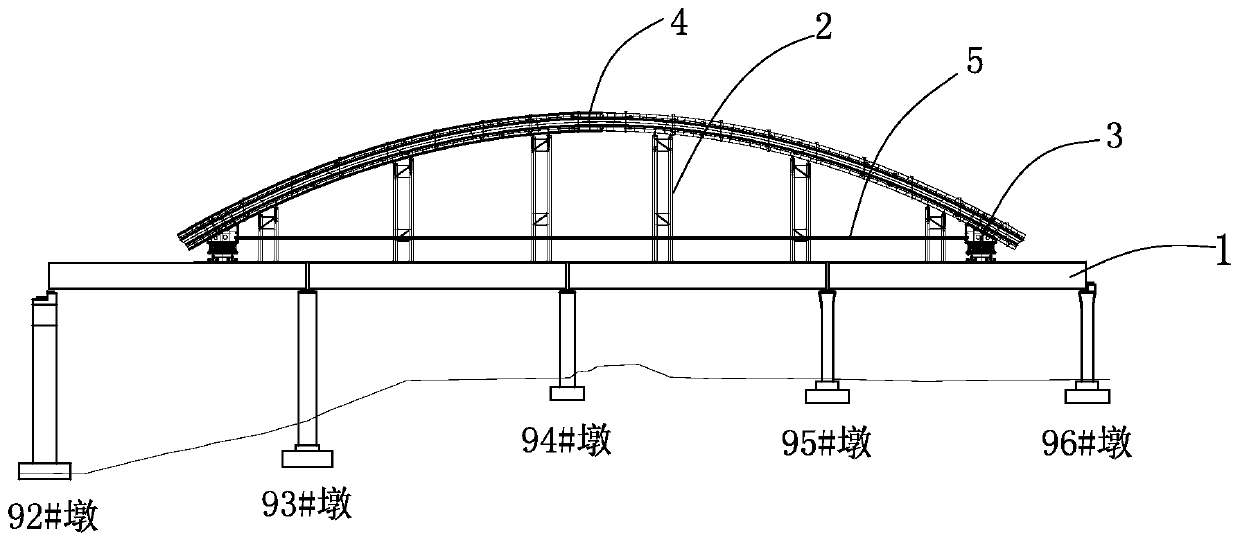
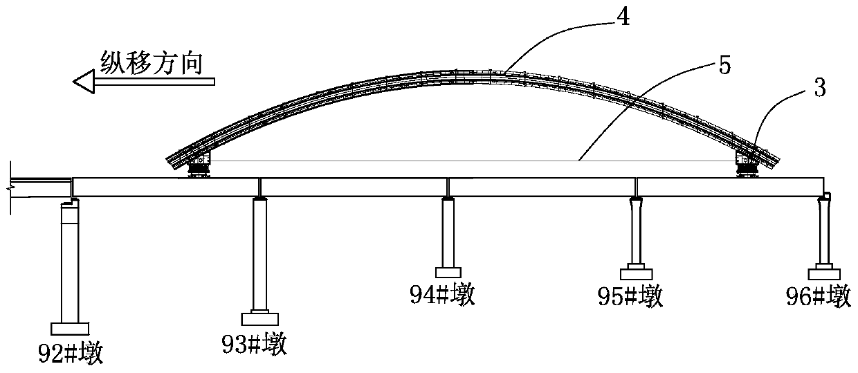
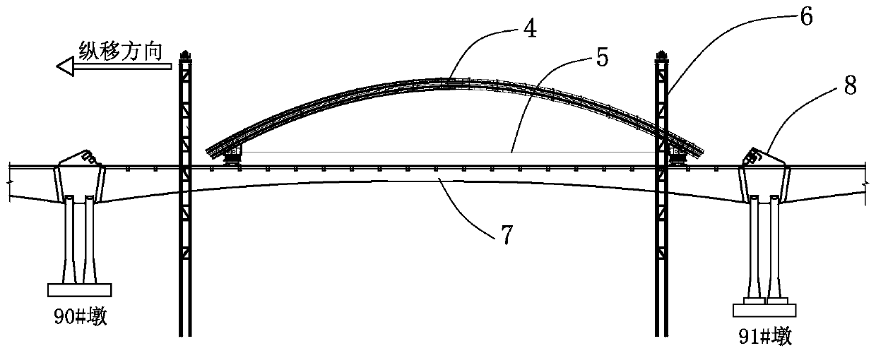
[0025] (1) Before the present invention starts construction, the design of the entire steel pipe arch is divided into the main arch section in the middle and the abutment sections at both ends, and the main arch section adopts the construction method of assembling the bridge head and moving longitudinally in place. When dividing the steel pipe arch, the weight of the main arch section is limited to not exceed the maximum bearing capacity of the main bridge steel girder; considering the influence of wind resistance on the steel pipe supply section during longitudinal movement, in addition to determining the main arch section according to the maximum bearing capacity of the main bridge body, The height of the main arch section can also be determined according to the transverse wind load. Avoid too high a height to cause structural instability during longi...


PUM


Abstract

The invention provides an overall longitudinal movement and lifting construction method for a large steel pipe arch, which comprises the steps: dividing the whole steel pipe arch into a central main arch section and abutment sections at both ends, wherein the weight of the main arch section is limited to not exceeding the maximum carrying capacity of a main bridge steel beam during division; assembling the main arch section on a main bridge approach bridge, wherein when a main bridge continuous beam is constructed, lifting towers for lifting the main arch section are respectively arranged at both ends of a main bridge, and after closure of the main bridge continuous beam is completed, the main arch section is smoothly, continuously and longitudinally moved to a designed lifting position ofa main span; installing the two abutment sections at both ends of designed abutment positions of the steel pipe arch, then lifting the main arch section to a designed installation position by using the lifting towers, and connecting with the two abutment sections, thereby completing the installation of the steel pipe arch. The invention is not limited by the bearing capacity of the main bridge steel beam and the height of a longitudinal movement section, and the applicable range of a traditional longitudinal movement method is greatly expanded.

Description

technical field [0001] The invention belongs to the field of bridge engineering, and relates to a construction method for installing a steel arch in a long-span continuous beam arch bridge by "beam first and then arch method". After the construction is completed, use the vertical moving trolley to move the steel arch vertically, and then use the lifting system to lift and adjust the designed installation position for closing. Background technique [0002] At present, the commonly used methods for constructing steel pipe arch bridges by the beam-first-arch method are as follows: The first method is the in-situ assembly method of brackets. This method has a large workload, low operating efficiency, and slow construction progress. It is only suitable for construction with small spans and heights. The second is the vertical rotation method, which has a large amount of temporary work, complex system transformation, difficult control, and slow construction progress, and is suitabl...

Claims


Application Information

Patent Timeline
Patent Type & Authority Applications(China)
IPC IPC(8): E01D21/00
Inventor 唐剑汪泉庆周彦文喻明灯刘杜宏高佳峰龚鹏鑫孙鹏
Owner ROAD & BRIDGE INT
Why Eureka
Try Eureka