
Reinforcing device and method for overweight reinforcement cage of ultra-deep underground diaphragm wall

A technology for underground diaphragm walls and reinforcement devices, which is applied in sheet pile walls, buildings, and infrastructure engineering, etc. It can solve problems such as quality and safety accidents, deformation and de-soldering, and large spot welding forces, so as to ensure overall rigidity and hoisting safety , prevent loosening or even falling off, and enhance the effect of tensile capacity

Inactive Publication Date: 2019-06-21
SHANGHAI FOUND ENG GRP
View PDF4 Cites 0 Cited by
  • Summary
  • Abstract
  • Description
  • Claims
  • Application Information

AI Technical Summary

Problems solved by technology

With the deepening of the ground wall, the reinforcement cage of the ground wall is lengthened, and the density of the reinforcement increases. When the reinforcement cage is hoisted, the spot welding force at the above position is relatively large, which is likely to cause deformation and de-soldering, which will lead to the overall deformation or even breakage of the reinforcement cage during the lifting process, resulting in quality problems. security incident

Method used


Image

  • Reinforcing device and method for overweight reinforcement cage of ultra-deep underground diaphragm wall
  • Reinforcing device and method for overweight reinforcement cage of ultra-deep underground diaphragm wall
  • Reinforcing device and method for overweight reinforcement cage of ultra-deep underground diaphragm wall

Examples


Embodiment Construction

[0020] The present invention will be further described below in conjunction with the accompanying drawings and embodiments.

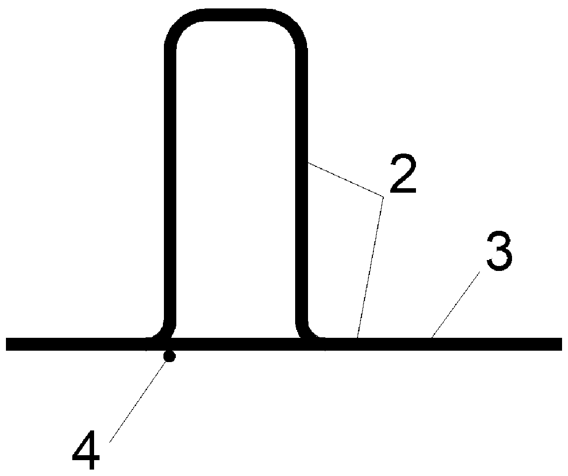
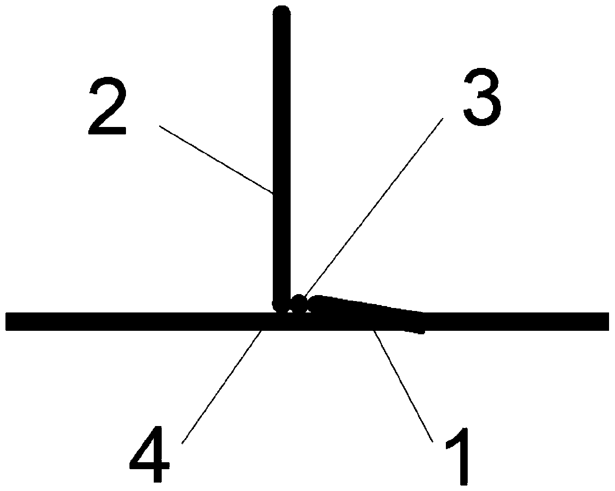
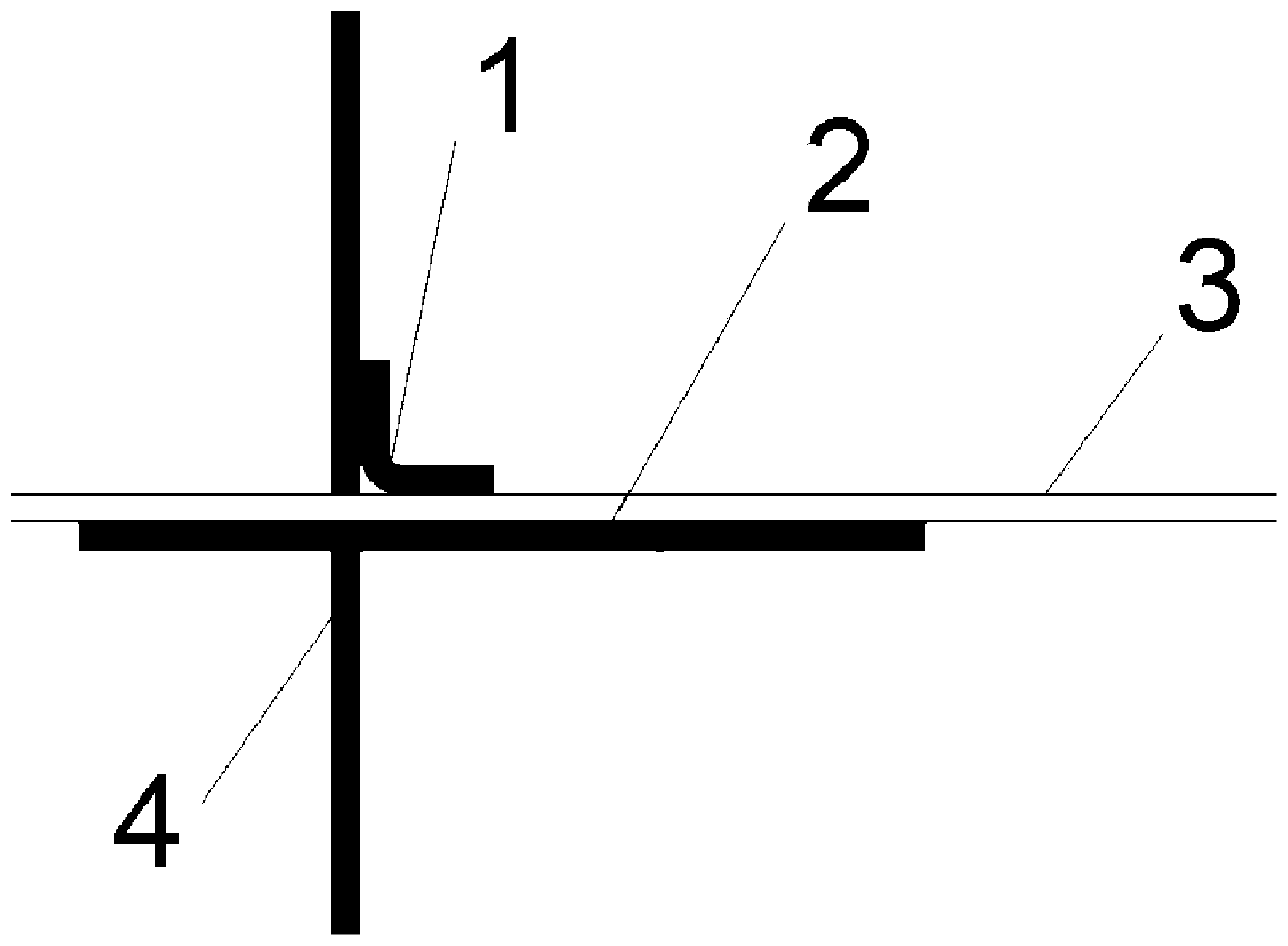
[0021] Such as Figure 1 to Figure 4 As shown, a super-heavy steel cage reinforcement device for an ultra-deep underground diaphragm wall includes a super-heavy steel cage, an L-shaped round bar 1, a U-shaped bar 2 at a lifting point, a main longitudinal bar 3 at a hanging point, and a horizontal truss bar 4 at a hanging point on the super-heavy steel bar cage. One end of the L-shaped round bar 1 is fully welded with the U-shaped bar 2 of the lifting point and the longitudinal main bar 3, and the other end is fully welded with the horizontal truss bar 4 of the lifting point at this position. The point U-shaped reinforcement is transferred to the longitudinal main reinforcement and the longitudinal truss reinforcement, and then to the horizontal truss reinforcement.

[0022] 10cm full welding is used between the left and right four sealing bars of the h...


PUM


Abstract

The invention relates to a reinforcing device and method for an overweight reinforcement cage of an ultra-deep underground diaphragm wall. The overweight reinforcement cage is provided with a liftingpoint U-shaped rib, a longitudinal main rib and a hoisting point horizontal truss rib. One end of the hoisting point horizontal truss rib is fully welded with the lifting point U-shaped rib and the longitudinal main rib, and the other end is fully welded with the hoisting point horizontal truss rib at the position. When the reinforcement cage is hoisted through the L-shaped reinforcing rib, pulling force is transmitted to the longitudinal main rib and a longitudinal truss rib from the hoisting point U-shaped rib and then transmitted to the horizontal truss rib. 10cm full-length welding is adopted between left and right four sealing ribs of the hoisting point horizontal truss rib and a horizontal rib, so that the problem that the sealing rib is infirm in connection and even fall off due tooverlarge stress deformation at the hoisting point and cracking of the welding points of the sealing rib and the horizontal rib when the reinforcement cage is lifted is solved. The method is a reinforcing measure provided in an ultra-deep underground diaphragm wall construction process for solving the problems that when an overweight reinforcement cage is hoisted, stress at a hoisting point is concentrated, deformation easily occurs, a reinforcement welding point is cracked, and the reinforcement cage integrally deforms and is even broken.

Description

technical field [0001] The invention relates to an overweight reinforcement cage in the construction of an ultra-deep underground diaphragm wall, in particular to an overweight reinforcement cage reinforcement device and method for the construction of an ultra-deep underground diaphragm wall. Background technique [0002] When making the steel cage of the underground diaphragm wall, the horizontal bars and horizontal truss bars are connected by spot welding on the outside of the longitudinal main bars. The U-shaped reinforcement at the lifting point, the longitudinal main reinforcement and the longitudinal truss can realize 10d full welding. When the steel cage is hoisted, the tension is transmitted from the shackle to the U-shaped reinforcement at the lifting point, and then to the longitudinal main reinforcement and truss reinforcement through full welding, while the other longitudinal main reinforcement is transmitted through the spot welding between the horizontal truss ...

Claims


Application Information

Patent Timeline
IPC IPC(8): E02D5/10E02D13/02
Inventor 韩泽亮於建文杨陆赵国伟
Owner SHANGHAI FOUND ENG GRP
Learn More