Anti-throwing building structure of nuclear power plant roof
A technology for building structures and workshops, applied in the field of nuclear engineering, which can solve the problems of increasing the load on the supporting structure and increasing the self-weight of the roof panel 1, and achieve the effect of simple and reasonable structural layout, reducing the self-weight, and meeting the structural design requirements
- Summary
- Abstract
- Description
- Claims
- Application Information
AI Technical Summary
Problems solved by technology
Method used
Image
Examples
Embodiment 1
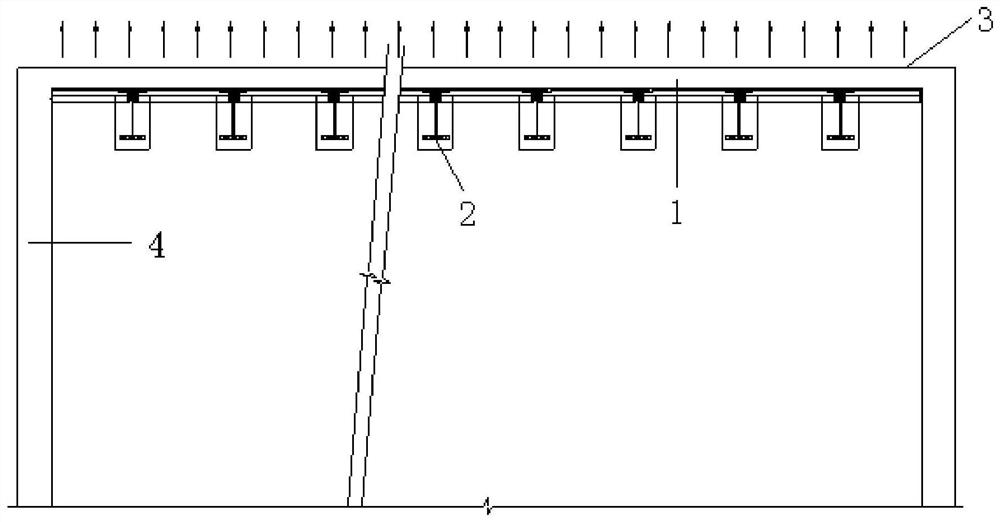
[0025] This embodiment provides an anti-throwing building structure for a roof of a nuclear power plant, including: a roof slab, a main beam disposed below the roof slab, and an anti-beam disposed above the roof slab, and the anti-beam is used to bear the upward throwing force of the roof slab.
[0026] The anti-throwing building structure of the roof of the nuclear power plant in this embodiment bears the upward throwing force of the roof slab through the anti-beam arranged above the roof slab. Compared with the method of simply increasing the thickness of the roof slab in the prior art, in this embodiment Under the premise of ensuring the design requirements, the method reduces the weight of the roof panel, saves manpower and material costs, and shortens the construction period. The anti-throwing building structure of the roof of the nuclear power plant in this embodiment not only meets the structural design requirements, but also is simple and reasonable in structural layout...
Embodiment 2
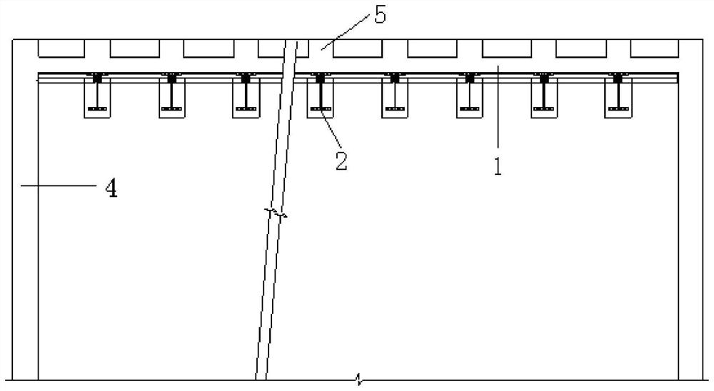
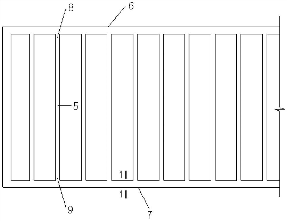
[0028] Such as Figure 2-4 As shown, the present embodiment provides an anti-throwing building structure for the roof of a nuclear power plant, including: a roof panel 1, a main beam 2 arranged below the roof panel 1, an anti-beam 5 arranged above the roof panel 1, and the anti-beam 5 is used To bear the upward throwing force of the roof panel 1.
[0029] Preferably, there are at least two main beams 2 and at least two reverse beams 5 . Specifically, there are more than two main beams 2 in this embodiment, and more than two reverse beams 5 .
[0030] It should be noted that the anti-beams 5 in this embodiment are arranged in parallel.
[0031] It should be noted that the anti-beam 5 in this embodiment is arranged corresponding to the main beam 2 , and the orthographic projection of the main beam 2 on the roof slab 1 overlaps with the orthographic projection of the anti-beam 5 on the roof slab 1 .
[0032] The spacing between the anti-beams 5 is arranged according to the spa...
Embodiment 3
[0042] Such as Figure 5 As shown, this embodiment provides a nuclear power plant roof anti-throwing building structure, and the difference between the nuclear power plant roof anti-throwing building structure in Embodiment 2 is: the nuclear power plant roof anti-throwing building structure in this embodiment, It also includes: a drainage board 11 arranged above the anti-beam 5 , and the drainage board 11 covers the anti-beam 5 , the roof panel 1 and the wall 4 .
[0043] Specifically, the roof panel 1 in this embodiment is a non-open-air roof panel, the drainage board 11 is a light drainage board, and the light drainage board is a profiled steel plate.
PUM
 Abstract
Description
Claims
Application Information
 - R&D
- Intellectual Property
- Life Sciences
- Materials
- Tech Scout
- Unparalleled Data Quality
- Higher Quality Content
- 60% Fewer Hallucinations
Browse by: Latest US Patents, China's latest patents, Technical Efficacy Thesaurus, Application Domain, Technology Topic, Popular Technical Reports.
© 2025 PatSnap. All rights reserved.Legal|Privacy policy|Modern Slavery Act Transparency Statement|Sitemap|About US| Contact US: help@patsnap.com


