A centering device for verifying or calibrating the installation of the flow meter to be tested

A centering device and flowmeter technology, applied in the field of measurement, can solve the problems of affecting the accuracy of verification or calibration, low efficiency, and inaccurate installation and alignment, and achieve the goal of eliminating potential safety hazards, accurate alignment, and ensuring accuracy of verification or calibration Effect

Active Publication Date: 2020-08-04
GUANGZHOU INST OF ENERGY TESTING
View PDF6 Cites 0 Cited by
  • Summary
  • Abstract
  • Description
  • Claims
  • Application Information

AI Technical Summary

Problems solved by technology

[0003] In order to solve the technical problems in the prior art that the alignment between the inspected flowmeter and the pipeline installation is not accurate enough during verification or calibration, multiple manual adjustments are required, affecting the verification or calibration accuracy, low efficiency, and potential safety hazards, the present invention provides a verification Or calibrate the flowmeter to be tested and install a centering device to achieve accurate centering, simple operation, and improve the accuracy of verification or calibration

Method used


Image

  • A centering device for verifying or calibrating the installation of the flow meter to be tested
  • A centering device for verifying or calibrating the installation of the flow meter to be tested
  • A centering device for verifying or calibrating the installation of the flow meter to be tested

Examples


Embodiment 1

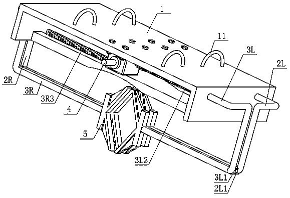
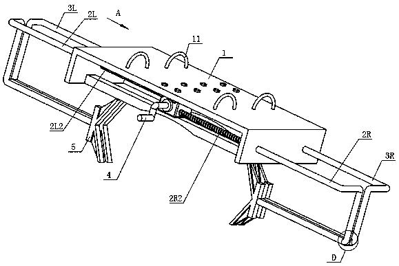
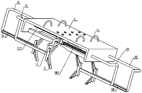
[0021] Such as figure 1 As shown in -8, a centering device for verifying or calibrating the flowmeter to be tested includes a frame body 1 and a rotating shaft 4 . The frame body 1 is U-shaped. The bottom of the frame body 1 faces upwards, the left and right sides are perpendicular to the bottom, and the frame body opening faces downwards. Hanging lugs 11 are connected to the outer surface of the bottom of the frame body 1 to facilitate the movement of the frame body 1 . A turbine case 12 is fixedly connected to the inner surface of the bottom of the frame body 1 .

[0022] The rotating shaft 4 is a cylinder, and the central axis is parallel to the left and right sides of the frame body 1 . The two ends of the rotating shaft 4 extend out of the turbine case 12 . Stretch out the rotating shaft 4 of worm case 12 front ends to be fixedly connected with rotating shaft handle.

[0023] figure 2 , 3 Among them, the end of the frame body 1 with the shaft handle on the rotatin...


PUM


Abstract

The invention, which relates to the technical field of measurement, provides a mounting centering device for verifying or calibrating a tested flow meter. The device comprises a frame body and a rotating shaft. The frame body is connected with a front connecting rod, a rear connecting rod, a left connecting rod and a right connecting rod respectively and symmetrically; connecting lead screws are fixedly connected to the upper ends of the connecting rods; and clamp claws are fixedly connected to the lower ends of the connecting rods. One pair of stepped turbines is fixedly connected to the rotating shaft; and the connecting lead screws are engaged with the stepped turbines respectively. A raised bar is fixedly connected to the front connecting rod; a groove is fixedly connected to the rearconnecting rod; and the raised bar and the groove are plugged. According to the invention, a technical problem that the verification or calibration precision is affected by the inaccuracy of the mounting centering of the tested flow meter and the pipeline in the verification or calibration and thus the potential safety hazard is caused in the prior art is solved. The device has the beneficial effects that: the accurate centering of the tested flow meter and the standard device pipeline is ensured and the verification or calibration accuracy is ensured; the manual intervention is avoided; the operation is simple; the device is used conveniently; the verification or calibration efficiency is improved; the labor intensity is reduced; and the potential safety hazard of the personal injury is eliminated.

Description

technical field [0001] The invention relates to the field of measurement technology, in particular to a device for aligning the tested flow meter with a pipeline when the tested flow meter is installed in verification or calibration equipment. Background technique [0002] Flow meters are widely used in various aspects such as industry, agriculture, national defense, scientific research, and people's production and life. They are important flow measurement instruments. The flowmeter is prone to measurement deviation due to the influence of the environment and other factors during use. Therefore, it is necessary to go to a third-party verification or calibration agency for verification or calibration within the specified period to ensure the reliability and accuracy of the flowmeter measurement. When verifying or calibrating the flowmeter, the flowmeter to be tested needs to be installed in the flow standard device. During the installation process, the center of the flowmete...

Claims


Application Information

Patent Timeline
Patent Type & Authority Patents(China)
IPC IPC(8): G01F15/18G01F25/00
Inventor 陈国宇钟灿鸣陈汉松胡候林
Owner GUANGZHOU INST OF ENERGY TESTING
Why Eureka
Try Eureka