
Remote monitoring system for traditional 3D printer

A remote monitoring system, 3D printer technology, applied in general control systems, control/regulation systems, program control, etc., can solve problems such as high prices, troublesome 3D printer work completion, and inability to complete the replacement process, and achieve low prices. , easy to use effect

Pending Publication Date: 2019-06-21
UNIV OF SCI & TECH LIAONING
View PDF0 Cites 0 Cited by
  • Summary
  • Abstract
  • Description
  • Claims
  • Application Information

AI Technical Summary

Problems solved by technology

[0002] After the traditional 3D printer imports the printing data, the working time of the printer is generally very long, even up to dozens of hours, so the workload of the user to monitor the 3D printer on the spot is relatively large, because the printing process of the 3D printer is not easy to appear. Fault, so when the user is working on the 3D printer, he usually does other things to wait for the 3D printer to complete the printing work, but it is difficult for the user to grasp the specific time when the 3D printer completes the work. If the user is far away from the 3D printer, go to check the 3D printer It is very troublesome to complete the work
At the same time, the remote control 3D printer currently developed can monitor and control the 3D printer through the network, but its price is relatively high, and it is not suitable for beginners of some 3D printers. , usually needs to replace the motherboard and change the program settings, so ordinary 3D printer users cannot complete the replacement process

Method used


Image

  • Remote monitoring system for traditional 3D printer
  • Remote monitoring system for traditional 3D printer
  • Remote monitoring system for traditional 3D printer

Examples


Embodiment Construction

[0024] The present invention will be described in detail below in conjunction with the accompanying drawings, but it should be pointed out that the implementation of the present invention is not limited to the following embodiments.

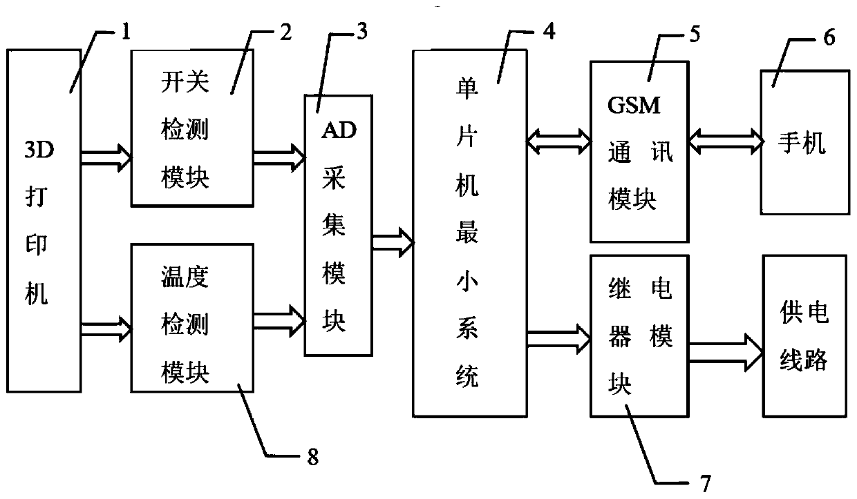
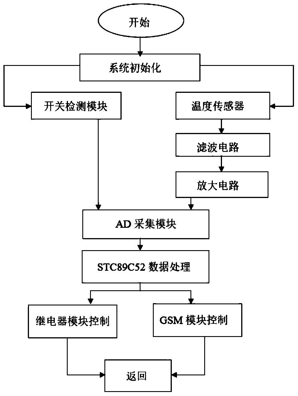
[0025] See Figure 1-Figure 4 , a remote monitoring system for traditional 3D printers, including a relay 7, a temperature detection module 8, an AD acquisition module 3, a GSM communication module 5, and a minimum single-chip microcomputer system 4;

[0026] The relay 7 is arranged on the power supply line of the 3D printer 1, and the signal line of the relay 7 is connected with the IO port of the single-chip microcomputer in the minimum system 4 of the single-chip microcomputer, so as to achieve the purpose of controlling the relay 7 of the minimum system 4 of the single-chip microcomputer, and is used to control the power supply of the 3D printer 1;

[0027] The main component of the temperature detection module 8 is a temperature sensor, and ...


PUM


Abstract

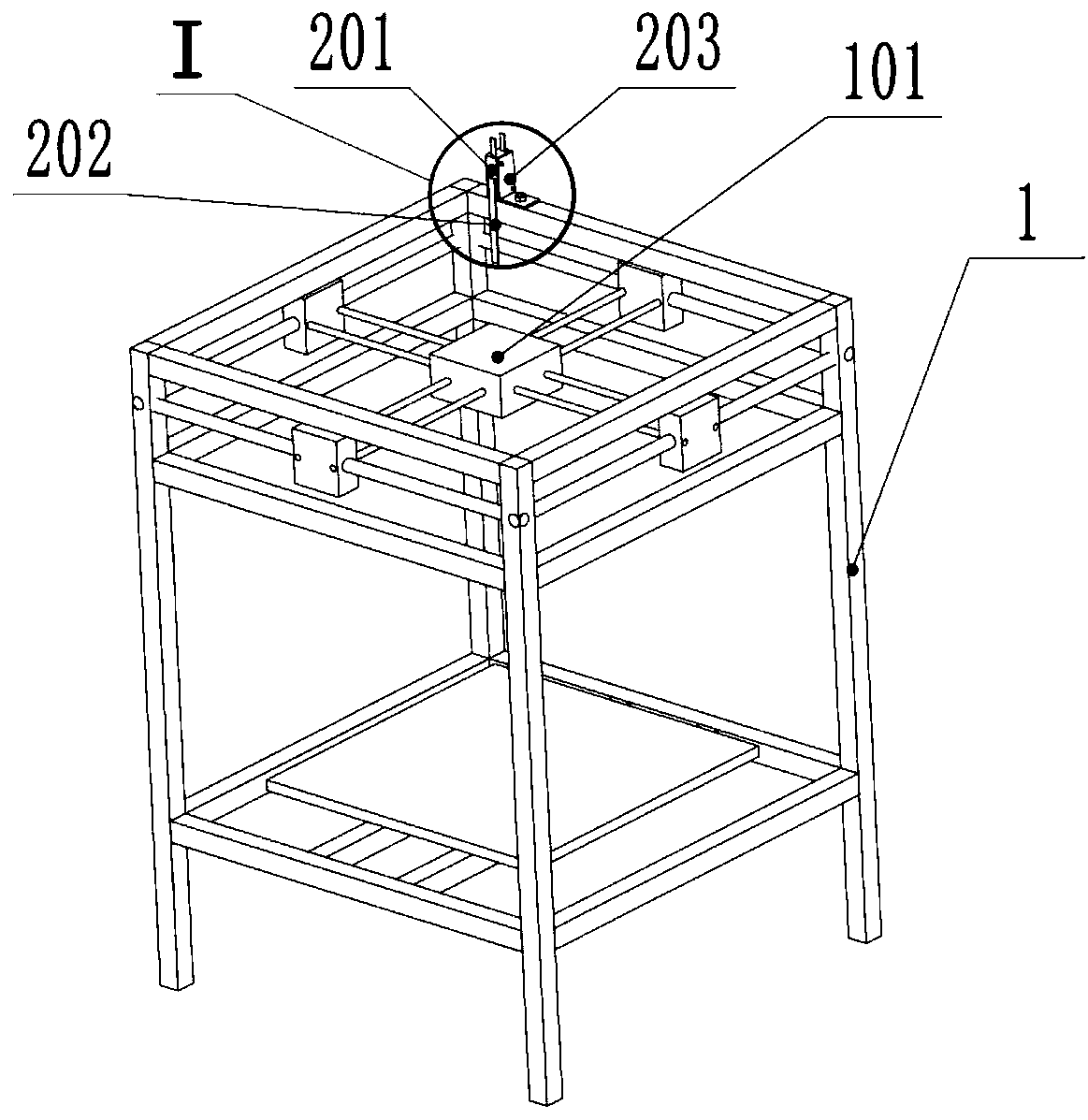
The invention relates to a remote monitoring system for a traditional 3D printer. The system comprises a relay, a temperature detecting module, an AD collection module, a GSM communication module, a single-chip microcomputer minimum system and a switch detecting module; the relay is arranged on the power supply line of the 3D printer; the signal line of the relay is connected with the IO port of the single-chip microcomputer minimum system; the temperature detecting module is fixed on the extrusion head of the 3D printer; the AD collection module is used for detecting the circuit voltage of the switch detecting module and the temperature detecting module; the switch detecting module comprises a closed loop which is formed by means of wire connection, wherein the closed loop is composed ofa micro switch, a direct-current power source, a resistor, and an LED light; the micro switch is installed on the upper surface cross beam of the 3D printer; when the slider of the 3D printer is reset, the slider presses the spring shifting sheet of the micro switch; and the LED lamp is used for verifying whether the switch detecting circuit works properly. The system of the invention has the advantages of convenient use and low price.

Description

technical field [0001] The invention belongs to the field of control of traditional 3D printers, in particular to a remote monitoring system for traditional 3D printers. Background technique [0002] After the traditional 3D printer imports the printing data, the working time of the printer is generally very long, even up to dozens of hours, so the workload of the user to monitor the 3D printer on the spot is relatively large, because the printing process of the 3D printer is not easy to appear. Fault, so when the user is working on the 3D printer, he usually does other things to wait for the 3D printer to complete the printing work, but it is difficult for the user to grasp the specific time when the 3D printer completes the work. If the user is far away from the 3D printer, go to check the 3D printer The completion of the work is very troublesome. At the same time, the remote control 3D printer currently developed can monitor and control the 3D printer through the network...

Claims


Application Information

Patent Timeline
IPC IPC(8): G05B19/042G01K13/00
Inventor 张峻巍胡彦庆陈发强于忠鑫白鑫鹏贾升边兰
Owner UNIV OF SCI & TECH LIAONING
Learn More