Mobile terminal antenna device

A mobile terminal antenna and input terminal technology, which is applied in the direction of antenna support/installation device, antenna, antenna grounding switch structure connection, etc., can solve the problem of inability to realize adjacent frequency and simultaneous broadband design, inability to achieve multi-frequency tuning, and unsuitable for miniaturized antennas and other issues to achieve the effect of realizing multi-antenna close-distance high-isolation design and realizing broadband/multi-frequency design

Pending Publication Date: 2019-06-21
SHENZHEN FIYTA PRECISION TIMER MFG +1
View PDF0 Cites 10 Cited by
  • Summary
  • Abstract
  • Description
  • Claims
  • Application Information

AI Technical Summary

Problems solved by technology

But there are design problems: the parasitic coupling uses a grounded parasitic body and the antenna body to achieve parasitic through electromagnetic radiation, but it cannot achieve multi-frequency tuning and has certain requirements for the coupling area of ​​the antenna body and parasitic branches, which is not suitable for miniaturized antenna design; The antenna active switch / variable capacitor can only tune the frequency band of a single antenna radiator, and cannot realize the simultaneous broadband design, and its design is still limited in the harsher environment

Method used


Image

  • Mobile terminal antenna device
  • Mobile terminal antenna device
  • Mobile terminal antenna device

Examples


Embodiment 1

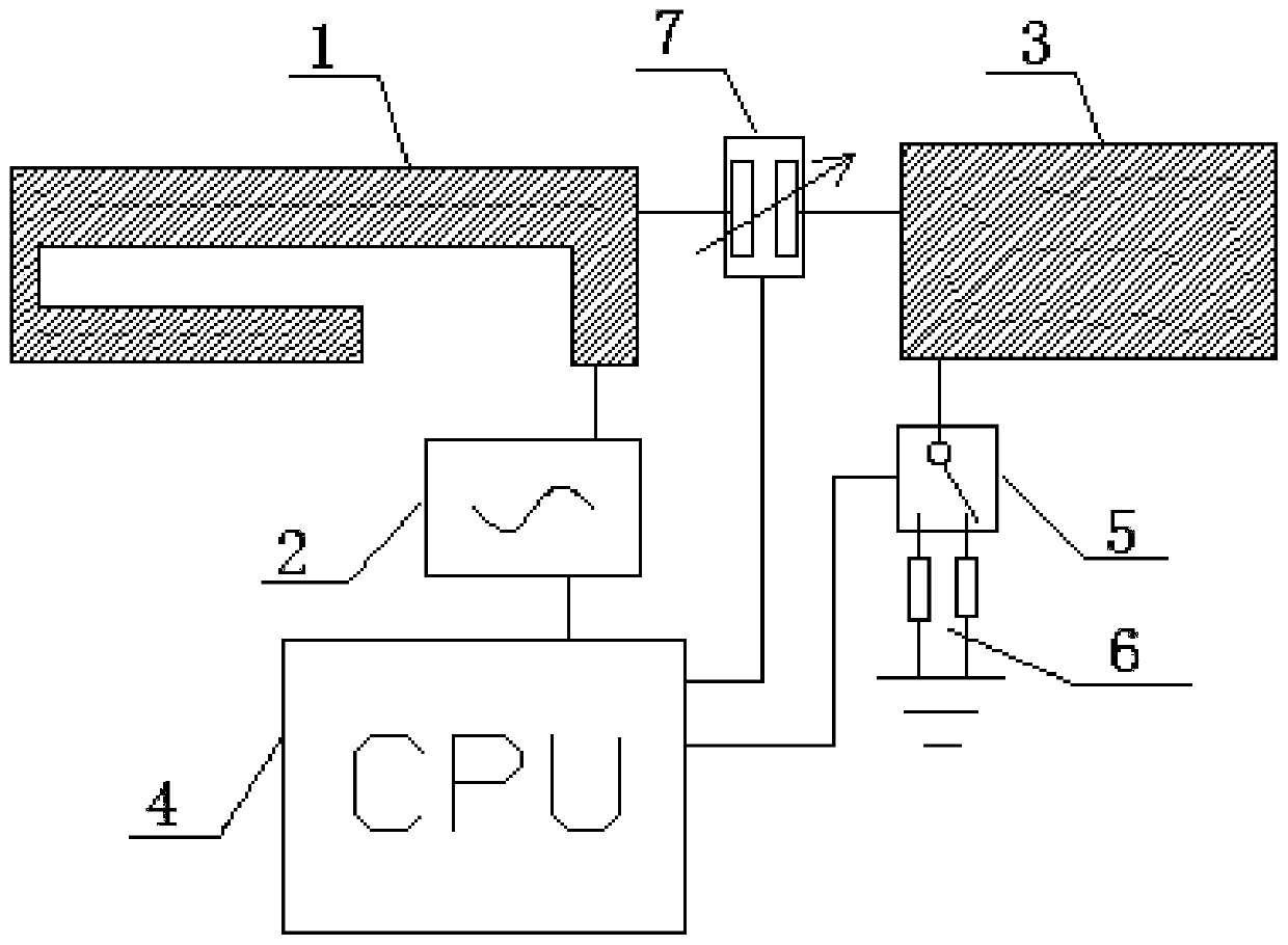
[0024] Embodiment 1: as figure 1 As shown, a mobile terminal antenna device includes a first radiator 1, the first radiator 1 is connected to the first signal output end of the processor 4 through a signal source 2, and one end of the second radiator 3 is connected to the second radiator 3 through a switch circuit. The first radiator 1 is connected, the other end of the second radiator 3 is grounded through the first active switch 5, the second signal output terminal of the processor 4 is connected to the control signal input terminal of the switch circuit, The third signal output terminal of the processor 4 is connected to the control signal input terminal of the first active switch 5, and the processor 4 controls the on-off of the switch circuit and the first active switch 5, Realize single-antenna multi-configuration form.

[0025] It also includes a matching device 6 through which the first active switch 5 is connected to the ground. The matching device 6 includes a capac...

Embodiment 2

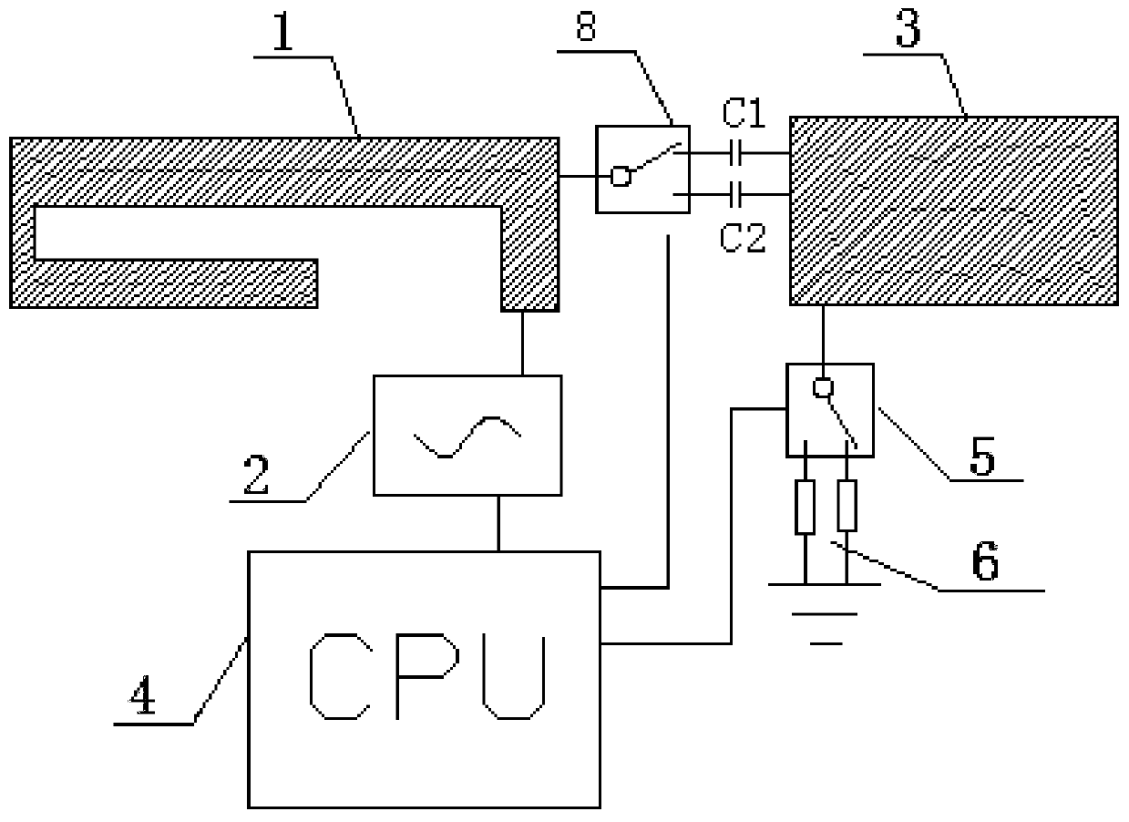
[0028] Embodiment 2: as figure 2 As shown, the structure of this embodiment is basically the same as that of Embodiment 1, except that the switch circuit is that the second active switch 8 is connected in series with more than two capacitors.

[0029] One end of the second active switch 8 is connected to the first radiator 1, and the other end of the second active switch 8 is connected to the second radiator 3 through the first capacitor C1 and the second capacitor C2 connected in parallel. connected, the signal output end of the processor 4 is connected to the control signal input end of the second active switch 8 .

[0030] In this embodiment, the first capacitor C1 has a large capacitance, and the second capacitor C2 has a small capacitance.

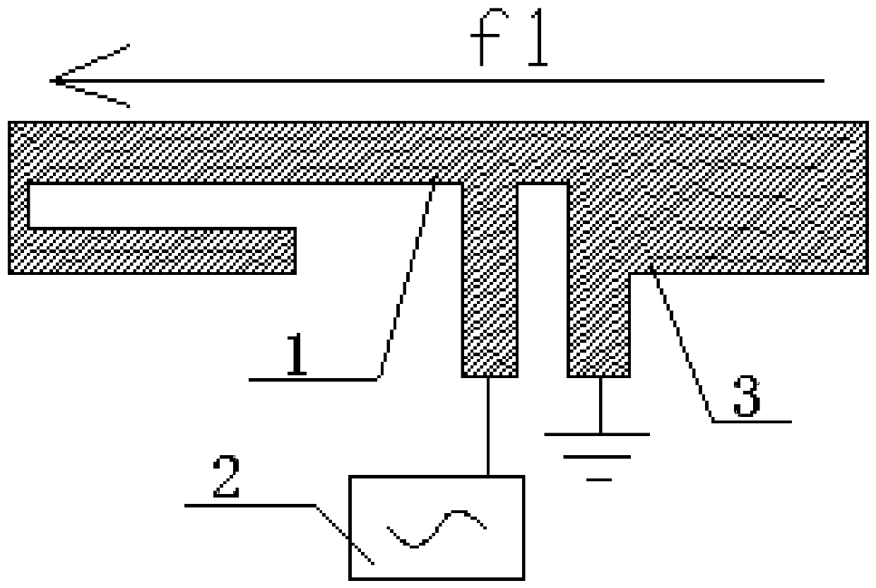
[0031] Such as image 3 As shown, when the first active switch 5 is grounded through the corresponding matching device 6, it can be equivalent to changing the shape of the second radiator 3, and the variable capacitor 7 is in a sma...


PUM


Abstract

The invention discloses a mobile terminal antenna device, and relates to the technical field of communication antennas. The mobile terminal antenna device comprises a first radiator; the first radiator is connected with the first signal output end of a processor through a signal source; one end of a second radiator is connected with the first radiator through a switch circuit, and the other end ofthe second radiator is grounded through a first active switch; and the second signal output end and the third signal output end of the processor are connected with the control signal input ends of the switch circuit and the first active switch respectively. Through the tuning design of a multi-antenna body by the switch circuit, the design that the parasitic frequency band is tunable, the antennaradiators are reconfigurable and multiple antennas are compatible in a low-radiation environment is realized, and multiple tunable schemes can be provided in a parasitic antenna and reconfigurable radiator mode, so that the broadband/multi-frequency design of the antennas and the near-distance high-isolation design of the multiple antennas are realized.

Description

technical field [0001] The invention belongs to the technical field of communication antennas, in particular to a mobile terminal antenna device. Background technique [0002] With the development of communication technology and Internet of Things technology, the carrier of mobile communication terminals has penetrated from mobile phones to various traditional industries, such as wearable products, IoT monitoring equipment, smart homes, etc. While the number of products requiring mobile communication functions increases, product design also faces diversified design requirements for terminals. Facing the design environment of miniaturized portable products or all-metal appearance products, the demand for miniaturization and broadband design of antennas is becoming increasingly obvious. [0003] As a conversion device for electromagnetic signals, the antenna design parameters such as radiation efficiency and coverage bandwidth depend on the clearance of the antenna and the su...

Claims


Application Information

Patent Timeline
Patent Type & Authority Applications(China)
IPC IPC(8): H01Q1/36H01Q1/50H01Q3/24H01Q23/00H01Q1/24
Inventor 陈廷龙桂华赵峰郭海龙
Owner SHENZHEN FIYTA PRECISION TIMER MFG
Why Eureka
Try Eureka