Plug-in assembly

A component and plug-in direction technology, which is applied to the parts, connections, and electrical components of the connecting device, can solve problems such as interference, increasing the height of the socket protruding from the outer surface of the appliance, and affecting the appearance of the circuit board, optical equipment, etc. , to avoid interference and reduce the total length

Active Publication Date: 2019-06-21
HUAWEI TECH CO LTD
View PDF5 Cites 15 Cited by
  • Summary
  • Abstract
  • Description
  • Claims
  • Application Information

AI Technical Summary

Problems solved by technology

[0004] But when figure 1 In the dust-proof socket shown, when plugging in the plug, the dust-proof door 04 is turned over to open the socket 03 in the socket housing 01, so a certain amount of space must be reserved in the socket housing 01, between the socket 03 and the ferrule 02. The length of the avoidance gap 05 allows the dust-proof door 04 to turn over, so the total length of the socket along the plug insertion direction is rel

Method used


Image

  • Plug-in assembly
  • Plug-in assembly
  • Plug-in assembly

Examples


Embodiment 1

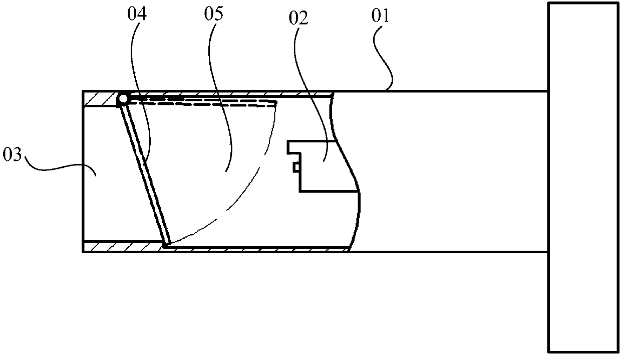
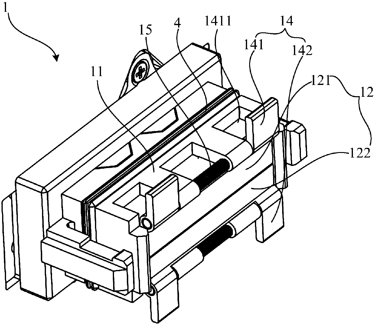
[0067] Such as image 3 As shown, one end of the door opening handle 14 is connected to the first end of the first dustproof door 12, and the other end extends radially outward along the socket 13 and out of the socket housing 11, as Figure 7 As shown, the pusher 22 extends along the insertion direction of the plug 2, and along the insertion direction of the plug 2, the front end of the pusher 22 protrudes from the front end of the first ferrule 21, and the inner side of the pusher 22 forms an escape space 23, The avoidance space 23 is located between the front end of the pusher 22 and the front end of the first ferrule 21, and an accommodation gap 24 is formed between the side wall of the front end of the first ferrule 21 and the pusher 22, and the accommodation gap 24 communicates with the avoidance space 23 ,Such as Figure 4 As shown, the first dustproof door 12 also includes a second end b opposite to the first end a, as Figure 8 As shown, in the process of moving the...

Embodiment 2

[0082] Such as Figure 29 As shown, the first end of the first dust-proof door 12 is connected to one end of the connecting rod 17, and the other end of the connecting rod 17 is hinged to the middle part of the socket housing 11 through the rotating shaft 18. The door opening handle 14 is a roller-shaped structure, and the roller One end of the structure is connected to the side of the first end of the first dust-proof door 12, and the other end extends outwards along the extension direction parallel to the rotating shaft 18 and out of the socket housing 11, as Figure 30 As shown, the pusher 22 is a fin structure extending along the insertion direction of the plug 2. Along the insertion direction of the plug 2, the front end of the fin structure forms a beveled edge, and the beveled edge is located at the front end of the first ferrule 21. On the front side, an avoidance space 23 is formed on the inner side of the fin structure. The avoidance space 23 is located between the f...


PUM


Abstract

The invention discloses a plug-in assembly, and relates to the technical field of signal connection structures. The plug-in assembly is invented for solving the problem that a dustproof socket in a plug inserting direction is relatively long in the prior art. The plug-in assembly comprises a socket and a plug; the socket comprises a socket shell and a first dustproof door; a jack is formed in oneend of the socket shell; a first dustproof door cover is arranged at the jack; the first end of the first dustproof door is rotationally hinged to the socket shell; a door opening handle is arranged on the first dustproof door; the plug comprises a first inserting core and a pushing piece; the pushing piece is connected to the first inserting core; and in the process that the plug is moved for inserting the first inserting core into the jack, the pushing piece can push the door opening handle to drive the first dustproof door to turn over outwards towards the jack so as to open the jack beforethe first inserting core is inserted in the jack. The plug-in assembly disclosed by the invention can be used for realizing connection between two optical fibers.

Description

technical field [0001] The present application relates to the technical field of signal connection structures, in particular to a plug-in assembly. Background technique [0002] In people's life, circuit boards, electronic equipment, optical devices, and optical equipment are well-known appliances, and sockets are required to be provided on these appliances for signal input or output. Because there is a socket on the socket, foreign matter such as dust in the environment can enter the socket through the socket. In addition, the opening area of ​​the socket is usually small, and it is difficult to clean the socket from the socket. After long-term use, dust is easy to accumulate in the socket. In the socket, it blocks the input or output signal, which seriously affects the transmission effect of the signal. In order to solve the above problems, it is very important to protect the socket from dust. [0003] example, figure 1 Shown is a kind of dust-proof socket in the prior ...

Claims


Application Information

Patent Timeline
IPC IPC(8): H01R13/52H01R13/502H01R24/00
Inventor 晏辉如齐义国孙宝亮邵云飞石君华长井贤次
Owner HUAWEI TECH CO LTD
Why Eureka
Try Eureka