
Door handle system for a motor vehicle

A technology for door handles and automobiles, applied in the field of door handle systems, can solve problems such as large working space, increased manufacturing costs, and easy wear and tear, and achieve the effect of compact structural space

Active Publication Date: 2019-06-21
WITTE AUTOMOTIVE GMBH
View PDF11 Cites 0 Cited by
  • Summary
  • Abstract
  • Description
  • Claims
  • Application Information

AI Technical Summary

Problems solved by technology

However, these microswitches have the disadvantages of requiring a relatively large amount of working space, being prone to wear and are susceptible to external factors such as vibrations, moisture or dust
But it requires the use of magnetic materials, which increases the manufacturing cost

Method used


Image

  • Door handle system for a motor vehicle
  • Door handle system for a motor vehicle
  • Door handle system for a motor vehicle

Examples


Embodiment Construction

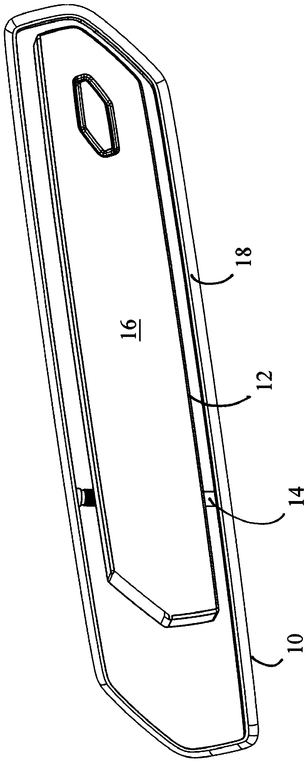
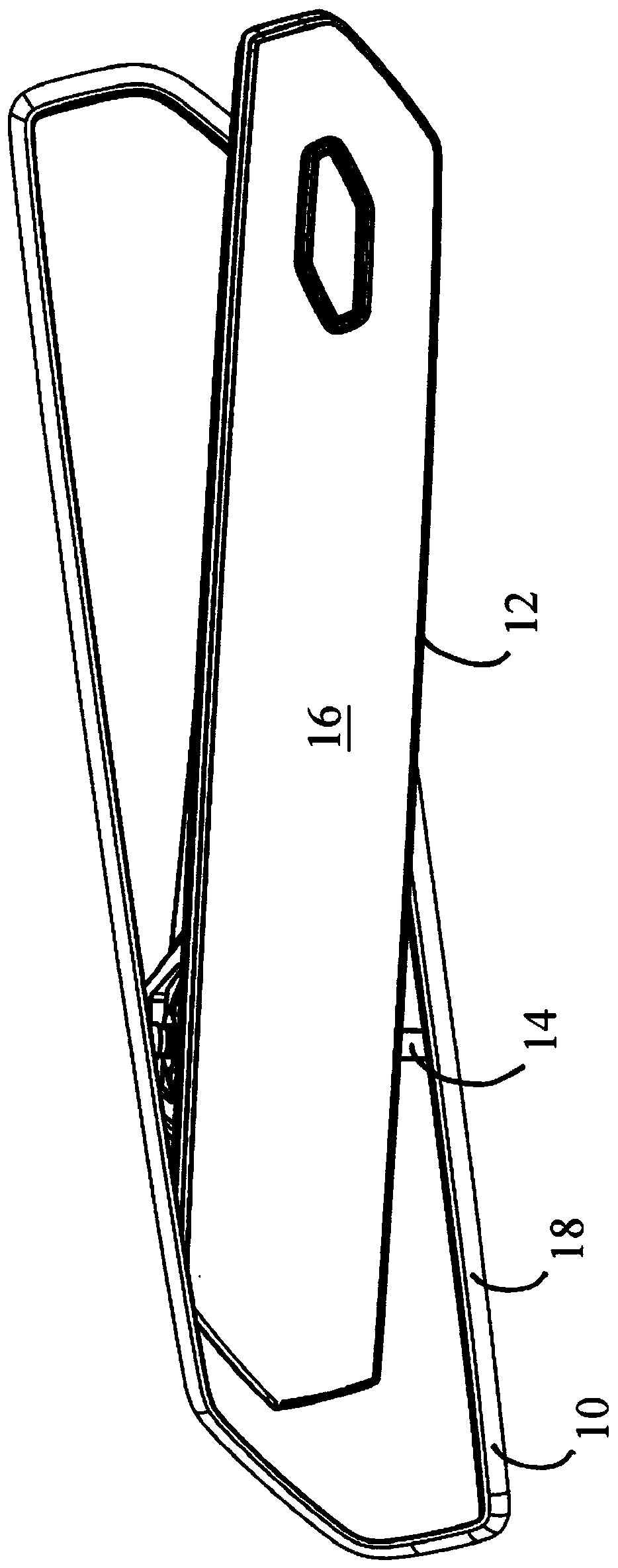
[0024] figure 1 A door handle system for a car is shown. In particular, the door handle system is suitable for fitting into a door, in particular the left side door of a motor vehicle. The door handle system comprises a fastening frame 10 and a handle part 12 , in the exemplary embodiment also an outside door handle, which is pivotably supported on the fastening frame 10 . In particular, the handle portion 12 is pivotable about a deflection axis 14 , which in the present embodiment is oriented substantially vertically. figure 1 The handle portion 12 is shown in a rest orientation in which it is fully received within the fixed bracket 10 such that the outer surface 16 of the handle portion 12 is generally flush with the outer edge 18 of the fixed bracket.

[0025] This means that the outer surface 16 of the handle part 12 in the rest position is flush with the outer panel of the vehicle when the fastening bracket 10 is inserted aligned in the outer panel of the vehicle.

[0...


PUM


Abstract

The invention relates to a door handle system for a motor vehicle, comprising a fastening bracket, at least one component which can be moved relative to the fastening bracket, and at least one sensorused to detect a position of the movable components relative to the fastening bracket.

Description

technical field [0001] The invention relates to a door handle system for automobiles, comprising a fixed bracket, at least one component movable relative to the fixed bracket, and at least one sensor for collecting the orientation of the movable component relative to the fixed bracket. Background technique [0002] Such door handle systems are known in principle. In this type of door handle system, a micro switch is usually used to acquire the orientation of a movable member or a plurality of movable members relative to a fixed bracket. However, these microswitches have the disadvantages of requiring a relatively large amount of working space, being prone to wear and are susceptible to external factors such as vibrations, moisture or dust. In existing solutions, Hall sensors can also be used to collect the orientation of the movable member. But it requires the use of magnetic materials, thereby increasing the manufacturing cost. Contents of the invention [0003] The ob...

Claims


Application Information

Patent Timeline
Patent Type & Authority Applications(China)
IPC IPC(8): E05B81/64E05B81/06E05B81/34E05B85/10E05B81/76
CPCE05B81/06E05B81/34E05B81/76E05B85/103E05B85/107E05B81/64
Inventor 马蒂亚斯·科赫妮科尔·利尔施
Owner WITTE AUTOMOTIVE GMBH
Learn More