Sliding component

一种滑动组件、滑动面的技术,应用在发动机元件、滑动接触轴承、轴承元件等方向,能够解决无法应对、被密封流体变质、危险等问题,达到提高吸入效果及吐出效果、防止干扰的效果

Active Publication Date: 2019-06-21
EAGLE INDS
View PDF7 Cites 5 Cited by
  • Summary
  • Abstract
  • Description
  • Claims
  • Application Information

AI Technical Summary

Problems solved by technology

[0005] Therefore, there is a problem that if different fluids exist on both sides of the sliding surface and the two fluids are mixed, there is a danger, or it is impossible to cope with the deterioration of the sealed fluid due to chemical reactions, etc.

Method used


Image

  • Sliding component
  • Sliding component
  • Sliding component

Examples


Embodiment 1

[0055] refer to Figure 1 to Figure 4 , the slide assembly according to Embodiment 1 of the present invention will be described.

[0056] In addition, in this embodiment, the case where the component constituting the mechanical seal is a slide component will be described as an example.

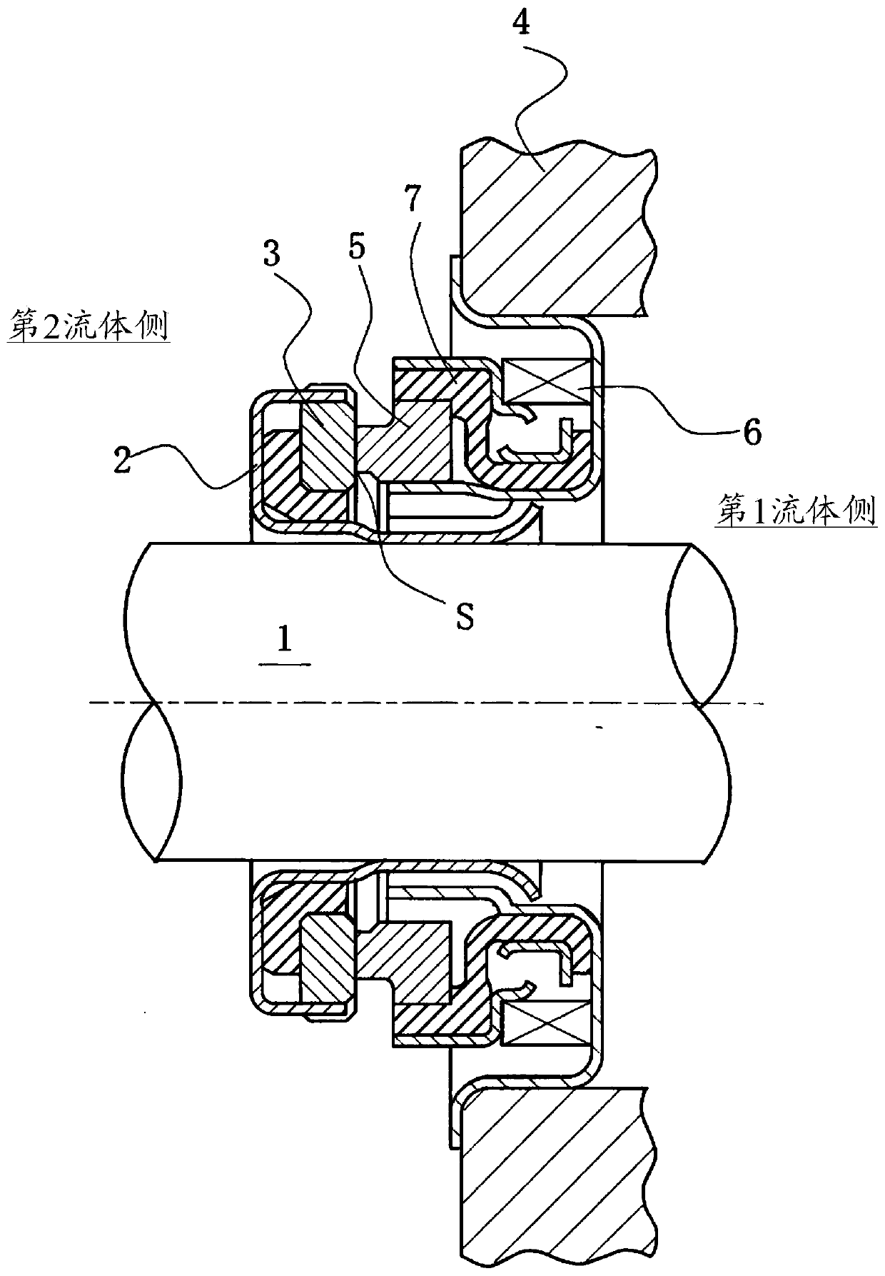
[0057] figure 1 It is a longitudinal sectional view showing an example of a mechanical seal. The first fluid exists on the inner peripheral side of the sliding surface S, and the second fluid exists on the outer peripheral side to achieve lubrication of the sliding surface and prevent the first fluid and the second fluid of different types from Mixing, for example, on the side of the rotating shaft 1 that drives the pump impeller (not shown) on the second fluid side, an annular rotating side seal ring 3 that can rotate integrally with the rotating shaft 1 through the sleeve 2, The annular fixed-side seal ring 5 provided in a non-rotating state and axially movable state in the pump casing 4 p...

Embodiment 2

[0101] refer to Image 6 , the slide assembly according to Embodiment 2 of the present invention will be described.

[0102] The difference between Embodiment 2 and Embodiment 1 is that the first fluid-side negative pressure generating mechanism is composed of a screw mechanism. The other basic structures are the same as Embodiment 1. The same components are marked with the same symbols, and repeated descriptions are omitted.

[0103] Image 6 Among them, the groove portion 21 of the screw mechanism 20 constituting the first fluid-side negative pressure generating mechanism has a curved (helical) shape that narrows toward the center from the upstream side toward the downstream side. Therefore, a negative pressure is generated in the groove portion 21 by sliding against the mating sliding surface, and the fluid sucked into the groove portion 21 is urged toward the first fluid side.

[0104] Image 6 In (a), the upstream end of the groove portion 21 is separated from the firs...

Embodiment 3

[0114] refer to Figure 7 , the slide assembly according to Embodiment 3 of the present invention will be described.

[0115] The difference between Embodiment 3 and Embodiment 2 is that the dynamic pressure generating mechanism is composed of a screw mechanism, and other basic structures are the same as Embodiment 2, and the same symbols are assigned to the same components, and repeated descriptions are omitted.

[0116] Figure 7 Among them, the groove portion 23 of the screw mechanism 22 constituting the dynamic pressure generating mechanism has a curved (helical) shape expanding from the upstream side toward the downstream side toward the second fluid side. Therefore, dynamic pressure (positive pressure) is generated in the groove portion 23 by sliding with the mating sliding surface, and the first fluid can enter between the sliding surfaces to increase the fluid film and improve the lubricating performance.

[0117] Figure 7 In (a), the upstream end of the groove por...


PUM


Abstract

Provided is a sliding component with which it is possible to prevent the mixing of different liquids on both sides thereof. The present invention is characterized in that: a sliding surface (S) is provided with a first-fluid-side negative pressure generation mechanism (12) comprising a first negative pressure generation groove (13), a second-fluid-side negative pressure generation mechanism (14) comprising a second negative pressure generation groove (15) and positioned closer to the second-fluid side than the first-fluid-side negative pressure generation mechanism (12), and a dynamic pressuregeneration mechanism (10) comprising dynamic pressure generation grooves (11) positioned closer to the first-fluid side and / or the second-fluid side than the first-fluid-side negative pressure generation mechanism (12) and the second-fluid-side negative pressure generation mechanism (14); the first negative pressure generation groove (13) is separated from the second-fluid side by land sections (R); and the second negative pressure generation groove (15) is separated from the first-fluid side by means of the land sections (R).

Description

technical field [0001] The present invention relates to a sliding assembly suitable eg for mechanical seals, bearings, other sliding parts. In particular, it relates to sliding components such as seal rings and bearings in which friction is reduced by intervening a fluid on a sliding surface and fluid leakage from the sliding surface needs to be prevented. Background technique [0002] In a mechanical seal as an example of a slide unit, fine grooves called texture rings may be provided on the sliding surface of the slide unit in order to improve lubricity. [0003] The applicant has applied for the following invention: First, in order to take into account both sealing and lubrication, for example, a spiral groove or a groove directly connected with the high-pressure fluid side is provided on the high-pressure side of the sliding surface of a pair of sliding assemblies that slide relative to each other. A positive pressure generating mechanism composed of indentations, a neg...

Claims


Application Information

Patent Timeline
Patent Type & Authority Applications(China)
IPC IPC(8): F16J15/34
CPCF16J15/3412F16J15/3404F16J15/40F16C17/045F16C33/107F16C33/741F16J15/34
Inventor 根岸雄大小杉纱和花井上裕贵井上秀行细江猛德永雄一郎
Owner EAGLE INDS
Why Eureka
Try Eureka