Fundus camera focusing structure

A camera and focusing technology, applied in ophthalmoscopes, eye testing equipment, medical science, etc., can solve the problems of unsatisfactory stability, increased camera cost, and screen shaking, etc., to achieve reliable and accurate judgment basis, Improve efficiency and quality, avoid image shaking effect

Pending Publication Date: 2019-06-25
河北智诠医疗器械有限公司
View PDF0 Cites 0 Cited by
  • Summary
  • Abstract
  • Description
  • Claims
  • Application Information

AI Technical Summary

Problems solved by technology

At present, the accuracy of many material-focused cameras cannot be controlled very accurately, and the screen may shake or blur in extremely subtle cases.
Commonly used SLR cameras or some camera lenses have two focusing structures, one is the lens motor type focusing structure, which can drive the internal lens group to move through the rotation of the lens to achieve zooming; the other is the motor built into the In the camera, the motor and the direction-changing gear drive the fixed lens group to move back and forth to achieve zooming; the traditional one is mostly the latter, the motor is built in the camera, and is located parallel to one side of the lens group, and the 180mm lens set in parallel is driven by a special gear. The lens group moves at an angle of 10 degrees. This structure can not only make the motor and lens group more compact, but also make the overall structure of the camera smaller. More importantly, through power steering, the lens that may be caused by the vibration of the motor output shaft is removed. group shaking; but because the steering gear still has the possibility of axial vibration, its stability cannot reach a perfect level; and in electronic cameras, more lens motor-type focusing structures are used, which pass the lens It is set to have a motor rotation drive structure, and the entire lens itself is used as a motor to provide a rotating power source, thus better solving the problem of lens shake
In many applications, a straight-rod camera structure is required. If a lens motor-type focusing structure is used, the manufacturing process and precision requirements of the lens-motor-type focusing structure are very high, not only the structural assembly complexity is high, but also will greatly increase the cost of the camera
However, when other existing focusing structures are applied to straight-rod cameras, axial shaking during the focusing process cannot be avoided, which reduces the shooting accuracy.

Method used


Image

  • Fundus camera focusing structure
  • Fundus camera focusing structure
  • Fundus camera focusing structure

Examples


Embodiment Construction

[0024] In order to have a clearer understanding of the technical features, purposes and effects of the present invention, the specific implementation manners of the present invention will now be described with reference to the accompanying drawings.

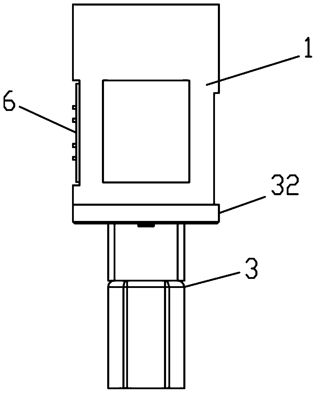
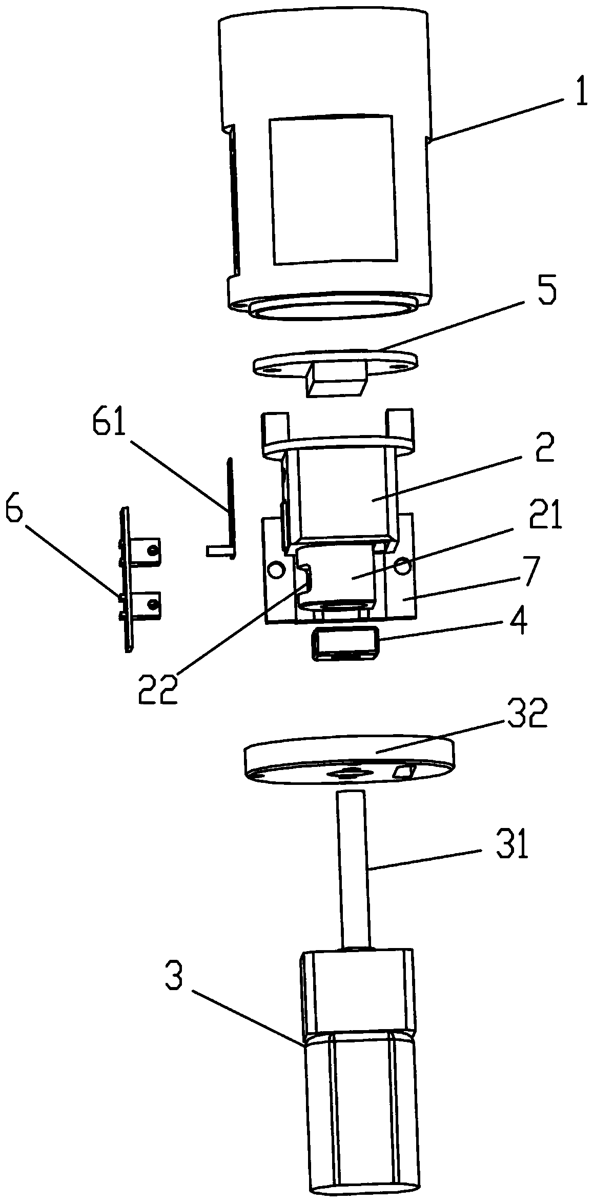
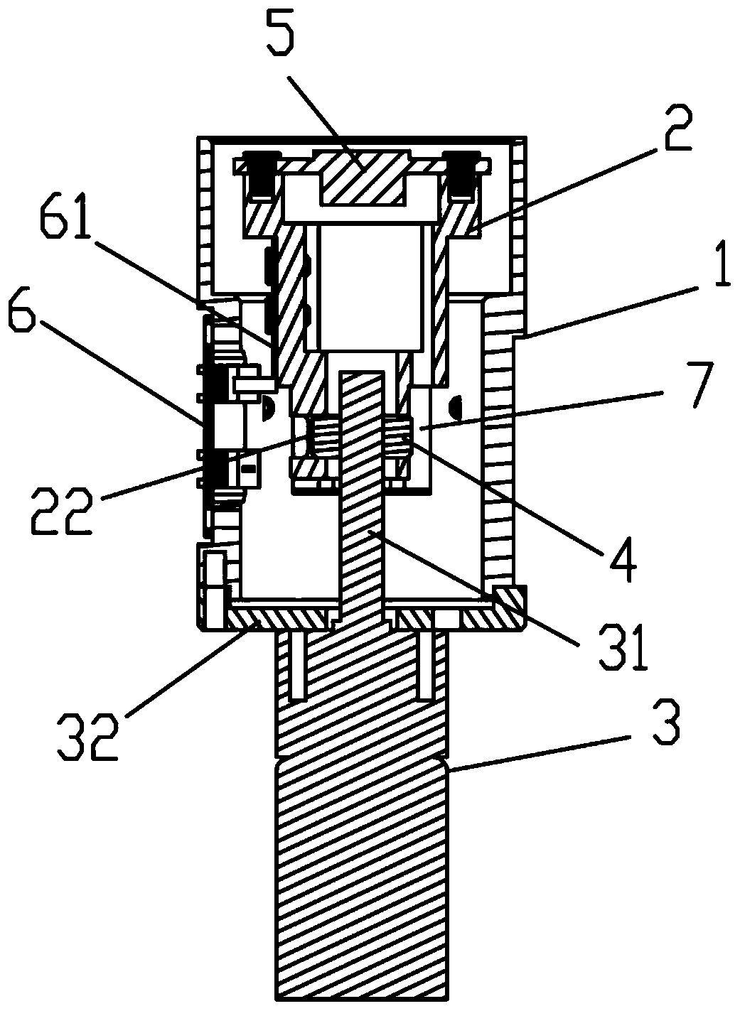
[0025] The focus adjustment structure of the fundus camera of the present invention can effectively suppress the lateral shaking problem during the focus adjustment process, improve the stability of the focus adjustment structure during the camera photographing process, and obtain extremely high definition and precision of images. Please refer to Figure 1 to Figure 3 As shown, a fundus camera focusing structure of the present invention, in its preferred embodiment, includes a motor 3, a bracket sleeve 1, a sensor 5, a sensor bracket 2 and a focusing rotor 4, and the bracket sleeve 1 is fixed Installed on the motor 3, the driving rod 31 of the motor 3 is arranged in the bracket sleeve 1; the middle part of the focusing rotor 4 is...


PUM


Abstract

A fundus camera focusing structure comprises a motor, a bracket sleeve, a sensor, a sensor bracket and a focusing rotor. The bracket sleeve is fixedly mounted on the motor, and a driving rod of the motor is disposed in the bracket sleeve. The middle portion of the focusing rotor is provided with a central wire hole. The driving rod of the motor is a screw, and the central wire hole of the focusingrotor is mounted on the driving rod via the threaded fit. The sensor bracket is disposed in the bracket sleeve, a driving rod sleeve is arranged at the bottom, and the driving rod sleeve sleeves thedriving rod. The side wall of the driving rod sleeve is provided with a transversely penetrating rotor hole, the focusing rotor is disposed in the rotor hole, and the focusing rotor can slide relativeto the driving rod sleeve in the direction perpendicular to the driving rod in the rotor hole. The sensor is fixed at the top of the bracket sleeve. The structure can effectively prevent the lateralsway of the straight rod type focusing structure and improve the focusing accuracy and clarity.

Description

technical field [0001] The invention relates to an image acquisition device, in particular to a linear fundus camera focusing structure without jitter that can realize high-precision shooting by the fundus camera. Background technique [0002] In the optical focusing camera structure, the accuracy of focusing is directly related to the quality of the camera or video. At present, the accuracy of many material-focused cameras cannot be controlled very precisely, and the screen may shake or blur in extremely subtle cases. Commonly used SLR cameras or some camera lenses have two focusing structures, one is the lens motor type focusing structure, which can drive the internal lens group to move through the rotation of the lens to achieve zooming; the other is the motor built into the In the camera, the motor and the direction-changing gear drive the fixed lens group to move back and forth to achieve zooming; the traditional one is mostly the latter, the motor is built in the came...

Claims


Application Information

Patent Timeline
Patent Type & Authority Applications(China)
IPC IPC(8): A61B3/12A61B3/15
Inventor 李亚峰
Owner 河北智诠医疗器械有限公司
Why Eureka
Try Eureka