
Elastic floating brake pad

A floating brake, elastic technology, applied in the direction of friction linings, brake types, brake components, etc., can solve the problems of cracks, defects, friction blocks not self-adjusting, unfavorable wear debris and friction heat, etc. Increase the area and volume, solve the eccentric wear of the brake pad, and improve the service life

Pending Publication Date: 2019-06-25
CRRC QISHUYAN INSTITUTE CO LTD
View PDF1 Cites 0 Cited by
  • Summary
  • Abstract
  • Description
  • Claims
  • Application Information

AI Technical Summary

Problems solved by technology

For fixed brake pads, the friction block cannot be adjusted by itself, and the friction performance is poor during high-speed braking, and the friction block is prone to cracks, defects, etc.; Chinese patent document CN103133570A discloses a combined floating brake pad, including plate, a number of friction blocks set on the back plate, an elastic support piece and a spring set between the friction block and the back plate, the elastic element of the brake pad can realize the elastic floating of the friction block and improve the friction performance of the brake pad , the friction block is in the shape of a regular hexagon. The contact between the sides of the friction block prevents the friction block from rotating. The gap between the friction blocks is small, which is not conducive to the discharge of wear debris and friction heat, resulting in excessive temperature of the brake pad during braking. Excessive buildup of wear debris

Method used


Image

  • Elastic floating brake pad
  • Elastic floating brake pad
  • Elastic floating brake pad

Examples


Embodiment 1

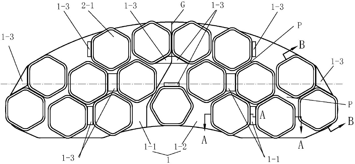
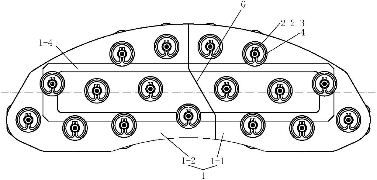
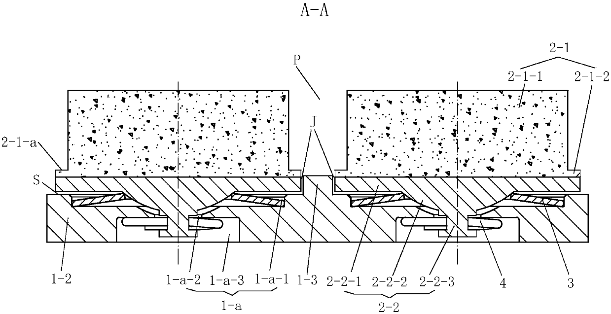
[0024] See Figure 1 to Figure 7 , this embodiment includes a mounting plate 1 and 17 friction blocks 2 arranged on the mounting plate 1, the friction block 2 has a support body 2-2 and a metallurgical powder friction body 2-1 fixed on the support body 2-2, so The friction body 2-1 is a regular hexagonal stepped column. The friction body 2-1 is composed of a friction body 2-1-1 and a friction chassis 2-1-2. The friction chassis 2-1-2 protrudes from the friction body 2-1. 1-1 forms a circle of edge 2-1-a, and the edge 2-1-a is used as a wear degree comparison surface. The shape of the friction main body 2-1-1 and the friction chassis 2-1-2 are similar, and the cross section is hexagonal shape, its six corners are arc angles. The height H of the friction chassis 2-1-2 is 2-5 mm. In specific applications, the height H is set according to user requirements. The ratio of the arc angle R1 of the friction body 2-1 to the length L1 of the opposite side is 0.18-0.22, and the ratio o...


PUM


Abstract

The invention discloses an elastic floating brake pad. The elastic floating brake pad comprises a mounting plate and a plurality of friction blocks, wherein the friction blocks are provided with supporting bodies and friction bodies, mounting holes are formed in the mounting plate, disc springs are arranged on the upper portions of the mounting holes, the supporting bodies penetrate through the disc springs to extend downwards, the supporting bodies are supported by the disc springs to realize up-down floating, clamping rings which are movably matched with the lower parts of the supporting bodies are arranged at the lower parts of the mounting holes, the friction bodies are regular hexagonal step columns and consist of friction main bodies and friction base plates, the periphery of each friction base plate extend out of the corresponding friction main body to form a circle of edge, the edges are used as wear degree comparison surfaces, chip removal channels are formed between the friction bodies, a chip removal network is formed by the staggered chip removal channels, the mounting plate is formed by splicing a left plate body and a right plate body, the left plate body and the right plate body are spliced along the edges of the friction blocks to form a zigzag line, a stop block which is fixed on the mounting plate and is used for limiting the rotation angle of the corresponding friction base plate is arranged on one side of each friction base plate, and the heights of the stop blocks do not exceed the heights of the friction base plates. According to the elastic floating brake pad, the brake pad can be prevented from eccentric grinding, chip removal and heat dissipation are facilitated, and the abrasion of the brake pad can be visually inspected.

Description

technical field [0001] The present invention relates to elastic floating pads. Background technique [0002] In the train disc brake system, the brake pad is one of the key components. When braking, the braking force is applied to the brake pad through the brake caliper, so that the friction block of the brake pad is in contact with the brake disc. Absorb kinetic energy and bring the train to a stop. During the braking process, a large amount of friction heat and wear debris are generated, and the wear debris is easy to accumulate in the gap between the friction block and the friction block. The brake pad is subjected to uneven temperature and thermal stress cycles, which will cause fatigue damage to the local position of the friction block, resulting in There are cracks, slag falling, and block falling on the friction block of the brake pad, which will affect the braking performance and the life of the brake pad. During the braking process of trains in ice and snow weathe...

Claims


Application Information

Patent Timeline
Patent Type & Authority Applications(China)
IPC IPC(8): F16D69/04F16D65/847
CPCF16D65/092F16D65/847F16D69/04
Inventor 翟财周潘祺睿朱松刘晓军谢鑫林杜利清苟青炳
Owner CRRC QISHUYAN INSTITUTE CO LTD
Learn More