Router with mobile antennas

A technology of mobile antennas and routers, applied in digital transmission systems, electrical components, transmission systems, etc., can solve the problems of short effective signal coverage distance, involving network cable adjustment, weakening signals, etc., to achieve improved signal coverage, small size, and structural simple effect

Inactive Publication Date: 2015-12-30
CHENGDU TOP DIAMOND TECH
View PDF3 Cites 0 Cited by
  • Summary
  • Abstract
  • Description
  • Claims
  • Application Information

AI Technical Summary

Problems solved by technology

[0004] The function of the antenna is to transmit and receive electromagnetic wave signals. The antennas equipped with existing wireless routers generally can only rotate in a fixed plane around the installation axis, and do not have other plane angle adjustment functions. Therefore, in order to ensure that the antenna can be in various situations The best angle to meet the wireless router Internet access speed and coverage standards, people sometimes have to move the main body of the wireless router to adjust the angle of the antenna in other planes
And moving the main body of the router often involves the corresponding adjustment of the network cable, which is very inconvenient
[0005] Moreover, due to the short effective coverage distance of the signal and the weakening of the signal by physical obstacles, the general wireless routers on the market often have weak signals and unstable network connections.

Method used


Image

  • Router with mobile antennas

Examples


Embodiment 1

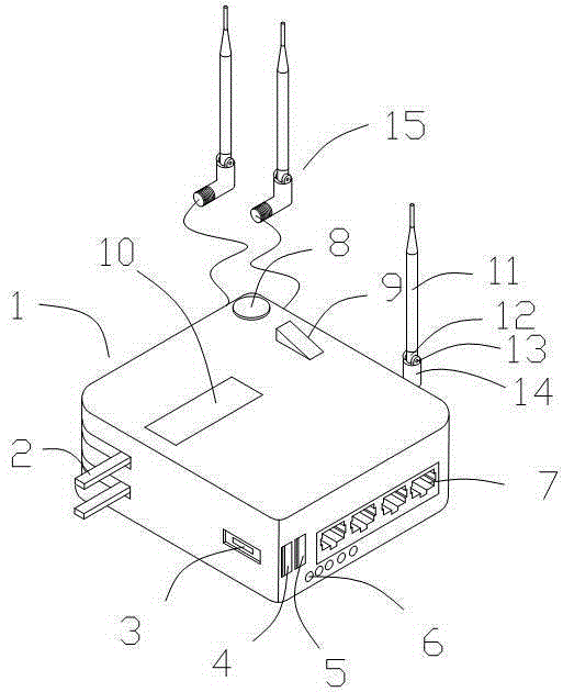
[0021] Such as figure 1 , this embodiment provides a router with a movable antenna, including a router body 1, the router body 1 is a cube structure, the router body 1 is provided with a signal input port 3 and four signal output ports 7, the The router main body 1 is hingedly provided with a charging head 2 that can be hidden in the router main body 1. The router main body 1 is provided with a power storage unit, and the router main body 1 is provided with a USB interface-4 and a USB interface with different output powers. 2. 5. The router main body 1 is provided with five power indicator lights 6, and the router main body 1 is provided with an LED light 8 and an LED light switch 9. An antenna lead-out tube 14 is fixedly installed on the side of the router main body 1, An angle adjustment shaft 13 is provided in the rotating sleeve at the outlet of the antenna lead-out pipe 14, and the angle adjustment shaft 13 is hinged to one end of the antenna hinge shaft 12, and the other...

Embodiment 2

[0025] Such as figure 1 As shown, this embodiment provides a router with a movable antenna, including a router body 1, the router body 1 is a cube structure, and the router body 1 is provided with a signal input port 3 and four signal output ports 7, The router main body 1 is hingedly provided with a charging head 2 that can be hidden in the router main body 1, and the router main body 1 is provided with a power storage unit inside, and the router main body 1 is provided with USB interfaces 4 and 4 with different output powers. USB interface 2 5, the router main body 1 is provided with 5 power indicator lights 6, the router main body 1 is provided with an LED light 8 and an LED light switch 9, and an antenna lead-out tube is fixedly installed on the side of the router main body 1 14. An angle adjustment shaft 13 is provided in the rotating sleeve at the outlet of the antenna lead-out pipe 14, and the angle adjustment shaft 13 is hinged to one end of the antenna hinge shaft 12,...

Embodiment 3

[0029] Such as figure 1 As shown, this embodiment provides a router with a movable antenna, including a router body 1, the router body 1 is a cube structure, and the router body 1 is provided with a signal input port 3 and four signal output ports 7, The router main body 1 is hingedly provided with a charging head 2 that can be hidden in the router main body 1, and the router main body 1 is provided with a power storage unit inside, and the router main body 1 is provided with USB interfaces 4 and 4 with different output powers. USB interface 2 5, the router main body 1 is provided with 5 power indicator lights 6, the router main body 1 is provided with an LED light 8 and an LED light switch 9, and an antenna lead-out tube is fixedly installed on the side of the router main body 1 14. An angle adjustment shaft 13 is provided in the rotating sleeve at the outlet of the antenna lead-out pipe 14, and the angle adjustment shaft 13 is hinged to one end of the antenna hinge shaft 12,...


PUM


Abstract

The invention discloses a router with mobile antennas, and relates to the technical field of routers. The router comprises a router body which is of a cube structure. A signal input port and four signal output ports are formed in the router body. A charging head capable of being concealed in the router body is hinged to the router body. An electricity storage unit is arranged in the router body. A first USB port and a second USB port different from the first USB port in output power are formed in the router body. Five electricity quantity indicator lights are arranged on the router body. An LED lamp and an LED lamp switch are arranged on the router body. An antenna leading-out tube is fixedly installed on the side face of the route body. An angle adjusting shaft is arranged in an outlet of the antenna leading-out tube in a rotating and sleeved mode and hinged to one end of an antenna hinging shaft. The other end of the antenna hinging shaft is fixedly connected with an antenna. The multiple mobile independent antennas are additionally arranged on the router body and connected with the router body through cables. The router has the advantages that the structure is simple, and the independent antennas enhance signals received by the router.

Description

technical field [0001] The present invention relates to the technical field of routers, in particular to a router with a movable antenna. Background technique [0002] A router, also known as a gateway device, is used to connect multiple logically separated networks. The so-called logical network represents a separate network or a subnet. When data is transferred from one subnet to another, it can be done through the router's routing function. Therefore, the router has the function of judging the network address and selecting the IP path. It can establish a flexible connection in a multi-network interconnection environment, and can connect various subnets with completely different data packets and media access methods. The router only accepts the source station or The information of other routers is an interconnection device at the network layer. [0003] As a hub device connecting various LANs and WANs in the Internet, routers have been widely used in various industries. ...

Claims


Application Information

Patent Timeline
IPC IPC(8): H04L12/771H04L45/60
CPCH04L45/60
Inventor 刘应龙
Owner CHENGDU TOP DIAMOND TECH
Why Eureka
Try Eureka