
Movable trolley for maintenance of power transmission and distribution equipment

A technology of power transmission and distribution equipment and mobile trolleys, which is applied in the direction of mechanical equipment, supporting machines, machine platforms/supports, etc., can solve the problems of high cost and high safety risk, and achieve low cost and use cost, good seismic performance, and artificial The effect of easy operation

Inactive Publication Date: 2019-06-25
焦红
View PDF0 Cites 2 Cited by
  • Summary
  • Abstract
  • Description
  • Claims
  • Application Information

AI Technical Summary

Problems solved by technology

[0002] At present, in the maintenance and overhaul of the power system, some heavy materials, such as the entire set of isolating switches, large-scale construction material accessories, disassembled switch components, knife gates, etc., are mainly completed by cranes and cars. High, and because the surrounding is a live environment, the safety risk is relatively large. Therefore, it is necessary to design a motorized device that is suitable for working in live places, has good seismic performance, is convenient to lift, has low cost and use cost, and is convenient for manual operation. Can not meet the needs of people in production and life

Method used


Image

  • Movable trolley for maintenance of power transmission and distribution equipment
  • Movable trolley for maintenance of power transmission and distribution equipment

Examples


Embodiment Construction

[0011] The following will clearly and completely describe the technical solutions in the embodiments of the present invention with reference to the accompanying drawings in the embodiments of the present invention. Obviously, the described embodiments are only some, not all, embodiments of the present invention.

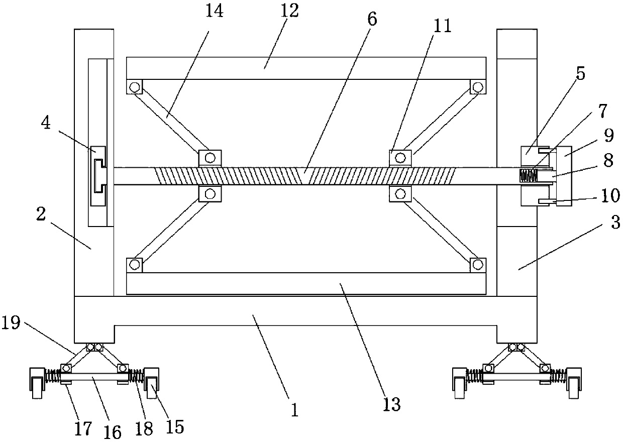
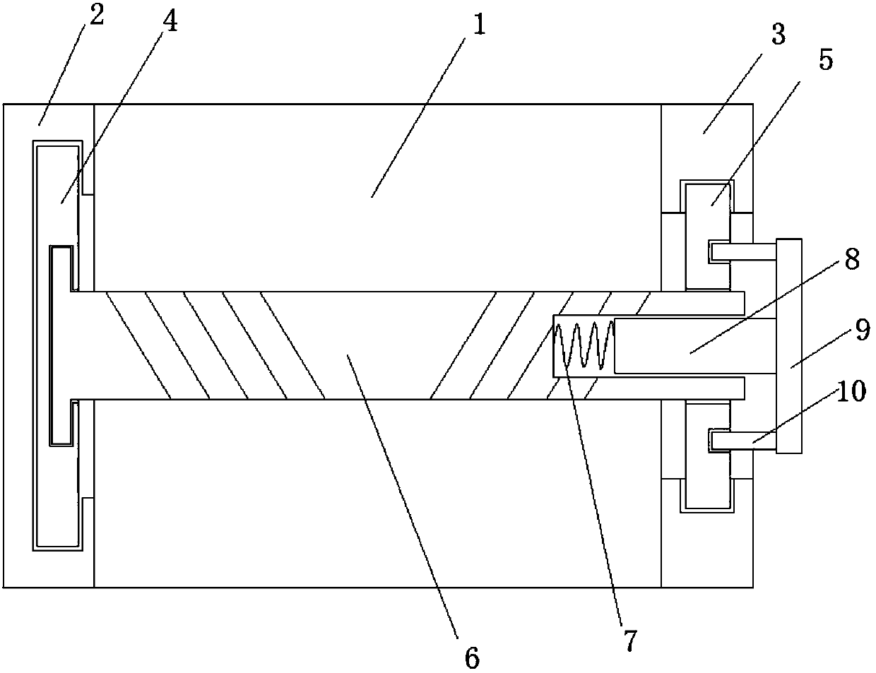
[0012] refer to Figure 1-2 , a mobile trolley for power transmission and distribution equipment maintenance, including a bottom plate 1, the two sides of the top of the bottom plate 1 are respectively connected with a vertical plate 1 2 and a vertical plate 2 3, the vertical plate 1 2 and the vertical plate 2 3 are arranged in parallel, and the vertical plate 1 2 The chute in the vertical direction is provided on the board body of the vertical board 2 and the vertical board 3. In the chute, a slide board 4 and a slide board 2 5 are slidingly connected respectively, and a two-way threaded rod is rotationally connected between the slide board 4 and the slide board 2 5....


PUM


Abstract

The invention discloses a movable trolley for maintenance of power transmission and distribution equipment. The movable trolley comprises a bottom plate, the two sides of the top of the bottom plate are connected with a first vertical plate and a second vertical plate correspondingly, the first vertical plate and the second vertical plate are arranged in parallel, moreover, sliding grooves in thevertical direction are formed in the plate bodies of the first vertical plate and the second vertical plate, a first sliding plate and a second sliding plate are connected in the sliding grooves in asliding mode correspondingly, a bidirectional threaded rod is rotationally connected between the first sliding plate and the second sliding plate, one end of the bidirectional threaded rod extends tothe side, far away from the first sliding plate, of the second sliding plate and is provided with a polygonal sliding groove, a polygonal sliding rod is slidably connected in the polygonal sliding groove, one end of the polygonal sliding rod is fixedly connected with a spring set, and the other end of the polygonal sliding rod extends to the side, far away from the first sliding plate, of the second sliding plate and is fixedly connected with a knob. The movable trolley can be applicable to work of live places, good in anti-shock performance, convenient and fast in lifting, convenient to operate manually, relatively low in manufacturing and use cost, and meets the use requirements of people in production and life.

Description

technical field [0001] The invention relates to the technical field of power transmission and distribution equipment, in particular to a mobile trolley for maintenance of power transmission and distribution equipment. Background technique [0002] At present, in the maintenance and overhaul of the power system, some heavy materials, such as the entire set of isolating switches, large-scale construction material accessories, disassembled switch components, knife gates, etc., are mainly completed by cranes and cars. High, and because the surrounding is a live environment, the safety risk is relatively large. Therefore, it is necessary to design a motorized device that is suitable for working in live places, has good seismic performance, is convenient to lift, has low cost and use cost, and is convenient for manual operation. It cannot meet people's needs in production and life. Contents of the invention [0003] The purpose of the present invention is to solve the shortcomi...

Claims


Application Information

Patent Timeline
IPC IPC(8): F16M11/42F16M11/24F16M11/04
Inventor 焦红
Owner 焦红
Learn More